


VAV-PRC003-EN 25
Zone Damper Selection Procedures
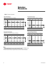
Refer to the sizing chart in Table 2 for
zone dampers. Follow down the first
column in the table for the desired
velocity. Then follow across for the cfm
(air volume) of a given VariTrac damper
based on that velocity.
Note: If the cfm exceeds the damper
range, increase the damper size.
Minimum airflow damper position
should be set to10 percent in heating or
cooling when a zone duct temperature
sensor is used for stand-alone control.
In addition, when controlling duct-
mounted electric reheat coils, cooling
minimum airflow should meet the
heating unit manufacturer’s guidelines.
(See Application Considerations,
Maximum System Effectiveness for
more details.)
Bypass Damper Selection Procedures
To determine the cfm capacity required
for a bypass damper, calculate
80 percent of the cfm capacity of
the heating/cooling unit.
Example: If the rooftop capacity is 1200
cfm, the bypass damper should be
sized for 1200 x .8 = 960 cfm.
To determine the size of the damper,
locate the recommended velocity and
cfm for the bypass damper.
Since a 10" round bypass damper at
1800 fpm provides 980 cfm, a 10"
damper at 960 cfm would be slightly
less than 1800 fpm, but still within the
1600 to 2000 fpm recommended
velocity. A 10" bypass damper is
selected.
Selection
Procedures
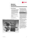
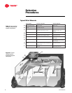
VariTrac dampers are typically installed
on VariTrac changeover bypass variable
air volume (VAV) systems. VariTrac is
ideal when applied to buildings which
use unitary HVAC units. The damper
units have controls, which vary air
volume and maintain appropriate duct
static pressure in the system to make
sure that all zones receive the right
amount of airflow.
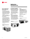
Trane offers four VariTrac dampers:
• Round zone dampers with DDC
controls
• Rectangular zone dampers with DDC
controls
• Round bypass dampers
• Rectangular bypass dampers
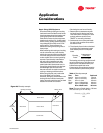
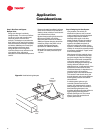
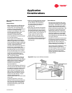
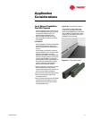
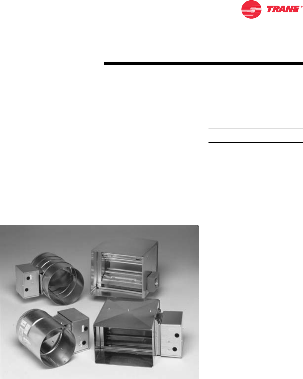
Figure 30. Round and rectangular zone and bypass dampers
VariTrac Dampers