


28 VAV-PRC003-EN
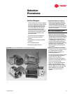
A
&
J
B
C
D
E
F
G
H
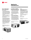
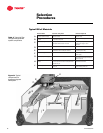
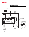
Figure 31. Typical
components in a
changeover-bypass
VAV system
Table 3. Typical VariTrac
changeover-bypass VAV
system components
Selection
Procedures
Typical Bill of Materials
Device Name Function in System Number Required
A
Central control panel
w/optional operator display
Controls the HVAC system and provides local
operator interface
One per HVAC unit/VariTrac system
(thermal zone)
Communicating bypass
controller
Sends supply duct temperature and pressure to
the central control panel
One per VariTrac system
Bypass damper(s) Supply air duct volume control to maintain
appropriate static pressure in the duct
One or two per system as needed to
bypass from supply to return
airstream
D
VariTrac dampers Varies air volume to the space to control comfort One per comfort zone
Zone sensors Sends space temperature and setpoint
information to the zone damper controller
One per comfort zone (DDC sensor
w/ LCD requires 4 VA)
CCP power supply 24V power for the central control panel The CCP must have a dedicated 24V
power supply
G
Zone damper power supply(s) 24V power for the zone dampers Power supplies may be shared; each
zone requires 10VA (plus the load of
optional outputs)
H
Trane rooftop communications
interface
Allows the CCP and Trane rooftop controller to
communicate with each other via simple twisted
shielded wire pair
One per controlled Trane rooftop
with ReliaTel controller
Optional relay board Provides 24V control of any non-communicating
HVAC unit
One per controlled non-
communicating HVAC unit
B
C
J
F
E