


38 VAV-PRC003-EN
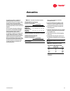
Table 10. CO
2
sensor specifications
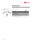
Table 9. Digital zone sensor specifications
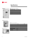
Specifications
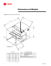
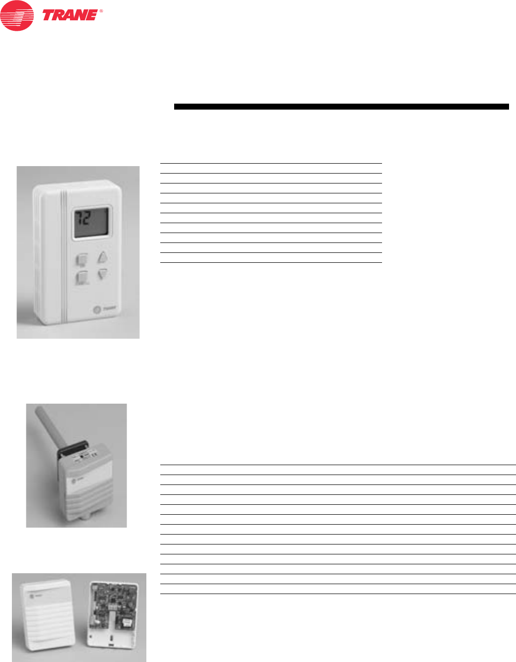
Figure 45. DDC zone sensor with
digital display
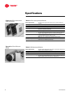
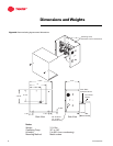
Figure 46. CO
2
duct sensor
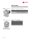
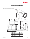
Figure 47. CO
2
wall sensor
Thermistor Resistance Rating 10kW at 77° (25°C)
Accuracy at 77°F (25°C) 0.4°F (0.2°C)
Setpoint Resistance Rating 500 Ohms at 70°F (21.2°F)
Display Zone Temperature Range 40°–99°F (10° to 35°C)
Display Setpoint Range 50°–90°F (10° to 32°C)
Operating Temperature 0°–120°F (–18° to 49°C)
Storage Temperature –20°–130°F (–29° to 54°C)
Humidity Range 5–95% non-condensing
Power Supply 24 VAC
Maximum VA Load 4 VA
Housing Material Rigid vinyl
Duct Wall
Dimensions 3 1/8" × 3 1/8" × 7 3/4" 4 1/4" × 3 1/8" × 1 7/16"
Operating Temperature 23°–113°F (–5°–45°C) 59°–95°F (15°–35°C)
Accuracy at 77°F (25°C) < ± (30 ppm CO2 + 3% of reading) < ± (40 ppm CO2 + 3% of reading)
Measuring Range 0-2000 parts per million (ppm)
Recommended Calibration Interval 5 years
Response Time 1 minute (0–63%)
Storage Temperature –4°–158°F (–20°–70°C)
Humidity Range 0 to 85% relative humidity (RH)
Output Signal (jumper selectable) 4-20 mA, 0-20 mA, 0-10 VDC
Resolution of Analog Outputs 10 ppm CO2
Power Supply Nominal 24 VAC
Power Consumption <5 VA
Housing Material ABS plastic