


15
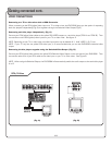
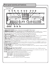
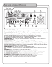
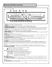
Rear panel controls and functions
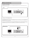
1. 5.1 CH. AUDIO OUTPUT jacks - These jacks are for connecting to 5.1 channel ready amplifiers/receivers. The
labels on each jack specify which speaker in your surround sound system to output to. CENT - center, SW - subwoofer,
SL- surround left, SR - surround right, FL- front left, FR- front right.
2. COMPONENT VIDEO OUT - These jacks output VIDEO to a TV monitor via COMPONENT VIDEO cables. COMPONENT
VIDEO outputs the different color signals (B and R) and luminance signal (Y) separately in
order to achieve high fidelity in reproducing colors. The description of the component video output
connectors might differ depending on the TV set or monitor (i.e. Pr/Pb/Y or Cr/Cb/Y or R-Y/B-Y/Y
etc.). Component video cables only transmit the video signal; separate cables are needed for audio sig
nals. Please refer to the operating instructions of the TV set or monitor for details.
3. AUDIO OUT (RCA) jacks - These audio output jacks provide analog AUDIO connections to external devices (A/V
receivers, TV’s, VCR’s etc.).
4. DIGITAL OUT (COAXIAL) jack - Connect a component here using a coaxial cable.
5. VIDEO OUT (RCA) jack - This jack outputs VIDEO to display device(s) i.e. TV’s, TFT’s and monitors.
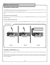
6. S-VIDEO jack - This jack outputs VIDEO to a display device (TV, TFT, etc) via an S-VIDEO cable. S-VIDEO provides bet-
ter color separation and a much cleaner signal by separating the color and picture parts of a composite-video signal.
7. DIGITAL OUT (OPTICAL) jack - This digital out is for connecting devices with an OPTICAL cable. Please make sure to
remove the protective cover from this jack prior to connecting an OPTICAL cable. When not using this input, keep the
protective cover on to protect it from dust and foreign material.
8. MASTER POWER switch - Use this switch to turn the master power on and off.
NOTE: If this switch is set to the OFF position, the POWER ON/STANDBY button will not be able to turn on the DVG-
909K.
9. VOLTAGE selector - Selects between 115V and 230V power settings.
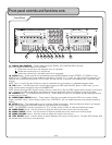
10. CABLE CONTROL jacks - These connect to the External Controller for the DVG-909K.
11. UNBALANCED MIC INPUTS (1/4”) - Connect microphones to these jacks using 1/4” microphone cables.
12. BALANCED MIC INPUTS (XLR) - Connect microphones to these jacks using XLR microphone cables.
13. SWITCHED VIDEO OUTPUT jacks - Output the video for both disc trays through this jack.
14. SWITCHED AUDIO (L/R) OUTPUT jacks - Output the L/R audio for both disc trays using these jacks.
15. FUSE terminal - This terminal houses the DVG-909K’s main system FUSE.
NOTE: If fuse replacement is necessary, only replace with the same type and rating of fuse.
16. AC IN connection - Connect AC Power Cord from the wall outlet to this connection.
10
11
12
13
14
15
16
9
8
1
2
4
5
6
7
3
Rear Panel