


9
EMX2000—Owner’s Manual
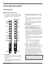
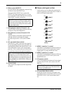
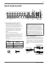
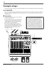
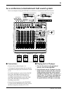
Input/output panel
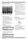
1 Channel input jacks (MIC, LINE) 1~8
These are the input jacks for channels 1~8.
By using the GAIN control (control panel 1)
you can connect any of the jacks to a wide range
of sources, from mics to line-level devices
(including synthesizers and rhythm machines).
The MIC jacks can provide +48V phantom
power, allowing you to use condenser micro-
phones.
Both MIC and LINE are balanced.
They are compatible with microphones of output
impedance 50~600Ω or line level devices of
600Ω. The nominal input level is –34 dB~+10 dB
for the LINE jacks, and –60 dB~–16 dB for the
MIC jacks.
Pin connections for the MIC and LINE jacks are
as follows:
* You can also connect a normal unbalanced phone plug.
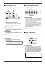
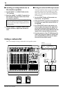
2 INS I/O (insert) jacks 1~4
These are TRS phone jacks that enable you to
insert an external effect processor, such as a com-
pressor/limiter, between the equalizer and fader
of input channels 1~4. These connections require
a special “Y” cable, such as shown in the follow-
ing diagram. The nominal input/output levels are
0 dB.
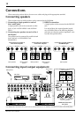
MONO
+4dB
FOOT SW
MONIMONI
(MONO)
PAMP
IN
2
EFFECT
+4dB
PHONES/
C-R OUT
(+4dB)
87654321
A
A
R
ST 1
L
RR
R
ST 2
1
L
L
REC
–10dBV
R
L
TAPE
R
L
L
ST
SUB 2
(MONO)
L
R
ST
SUB 1
(MONO)
11 L
12 R
11/12
A
A
B
B
B
B
INSERT I/O
OUT IN
0dB
(MONO)
9 L
9 L
10 R
11 L
12 R
10 R
LINELINELINELINELINE
INS
I/O
INS
I/O
INS
I/O
INS
I/O
LINELINELINE
MIC MIC MIC MIC MIC MIC MIC MIC
INPUT OUTPUT
9/10
+4dB+4dB+4dB BRIDGE
+4dB
+4dB
+4dB
B9
C8
3 426
0
A
57
1
MIC jacks
(XLR type)
LINE jacks
(TRS phone jacks) *
Pin 1: ground Sleeve: ground
Pin 2: hot (+) Tip: hot (+)
Pin 3: cold (–) RIng: cold (–)
GND
RST
+-
GND
+-
Note: It is not possible to simultaneously use
both the MIC and LINE inputs of a given
channel. For each channel, use only one of the
inputs as appropriate for the input source.
Phantom power is switched on/off simulta-
neously for channels 1~8. For this reason, de-
vices (in particular, unbalanced devices) other
than condenser microphones must be con-
nected to the LINE jacks of channels 1~8 or
channel 9/10~11/12 input jacks if the PHAN-
TOM +48V switch (control panel Y) is on.
to the input jack of
the external processor
to the output jack of
the external processor
to the INS I/O jack
Tip
Tip
Ring
Sleeve
Sleeve