


7
EMX2000—Owner’s Manual
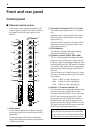
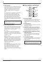
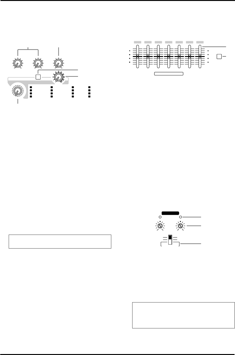
■ Digital effect section
This section enables you to turn the built-in digi-
tal effect on/off and select the effect type.
M MONI 1/2 (monitor 1/2) control
This knob adjusts the level of the return signal
that is sent from the built-in digital effect to the
MONITOR 1/2 buses.
N ST (stereo) control
This knob adjusts the level of the return signal
that is sent from the built-in digital effect to the
STEREO bus.
O Effect selector
This knob selects the effect type for the internal
digital effect.
P ON switch
This switch turns the internal digital effect on/
off.
Q Effect control
This knob adjusts the time parameter of the
internal digital effect.
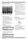
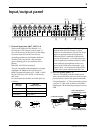
■ Graphic equalizer section
This section enables you to adjust the tone of the
STEREO bus signal.
R Graphic equalizer
This is a 7-band graphic equalizer that allows you
to adjust the frequency response of the STEREO
bus signal, providing a maximum of ±12 dB of
cut/boost for each frequency band.
This graphic equalizer affects both the STEREO
bus signal that is output to the speakers and the
line level signal that is output from the ST 1/2
jacks (input/output panel 8), and MONO jack
(input/output panel 0).
S ON switch
This switch turns the graphic equalizer on/off.
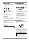
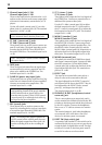
■ Power amp section
This section allows you to select the signals that
will be input to the built-in two-channel power
amplifier.
T LIMITER indicator
This indicator lights up when the level of the sig-
nal output from the power amp section reaches
the maximum and the limiter is activated. Adjust
the LEVEL control U and appropriate fader so
that the indicator lights up for only a short while
when the signal reaches the maximum level.
Note: The master EFFECT fader setting does
not affect the internal digital effect signal.
VOCAL ECHO 1
VOCAL ECHO 2
VOCAL ECHO 3
VOCAL ECHO 4
DIGITAL EFFECT
MAXMINPROGRAM
100
ST
100
ON
MONI 2
10
10
9
7
8
11
12
13
14
15
16
2
3
4
5
6
1
0
MONI 1
VOCAL REVERB 1
VOCAL REVERB 2
VOCAL REVERB 3
VOCAL REVERB 4
HALL 1
HALL 2
HALL 3
ROOM
PLATE 1
PLATE 2
PLATE 3
GATE REVERB
1
2
3
4
5
6
7
8
9
10
11
12
13
14
15
16
M N
O
Q
P
Note: The indicator lights up or flashes for a
longer duration if the power amp section is sig-
nificantly overloaded, which could result in
malfunction. Avoid such a situation.
GRAPHIC EQUALIZER
6
0
6
ON
8k4k2k1k500250125
+12
–12
6
0
6
+12
–12
R
S
MONO BRIDGE
POWER AMP
LIMITER
LR
LEVEL
L/BRIDGE
ST L
MONI 1
ST R
MONO
+4+18
+4+18
U
T
V