


8
EMX2000—Owner’s Manual
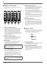
U LEVEL controls
These knobs enable you to adjust the level of the
signals input from the mixer section to the power
amp section. Rotating the knob clockwise will
raise the level of the input signal. Use a screw-
driver of a width of 3mm or less to adjust the
knob.
If an external piece of equipment is connected to
the P.AMP IN jacks (input/output panel 6),
these knobs adjust the input sensitivity of the
power amp (the input level that will provide the
maximum output level in the power amp sec-
tion). The sensitivity range is +18 dB~+4 dB, and
rotating the knobs clockwise raises the input sen-
sitivity.
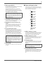
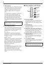
V Power amp select switch
Select one of the following three settings to spec-
ify the signals to be routed to the corresponding
jacks according to the speaker connection at the
SPEAKER jacks 1 on the rear panel.
• ST L-ST R
The STEREO bus signals are output from the
SPEAKERS L 1/2 jacks and the SPEAKERS R 1/2
jacks. The final level of these signals is adjusted by
the master ST 1 fader.
• MONI 1-MONO
The MONITOR 1 bus signals are output from the
SPEAKERS L 1/2 jacks, and a monaural signal
that is a mix of the STEREO bus signals is output
from the SPEAKERS R 1/2 jacks. The final level of
these signals is adjusted by the master MONI 1
fader and the MONO fader.
• MONO BRIDGE
The monaural signal that is a mix of the STEREO
bus is output from the BRIDGE jack. The final
level of this signal is adjusted by the master
MONO fader. Set the switch to this position
when you connect only one speaker to play a loud
sound.
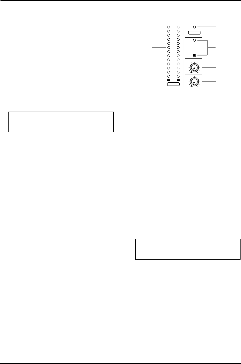
■ Other indicators and controls
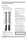
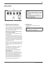
W Peak level indicator
This indicator allows you to monitor the level of
the signal output from the ST 1 jacks. The “0”
indicator lights up when the ouput level reaches
+4 dB.
X POWER indicator
This indicator will light up when the power of the
EMX2000 is turned on.
Y PHANTOM (+48V) switch and indicator
This switch turns the phantom power supply on/
off for the MIC input jacks for channels 1~8.
When this switch is on, the indicator lights up.
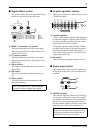
Z PHONES/C.R.OUT (headphones/control
room out) control
This knob adjusts the level of the signal moni-
tored via the PHONES/C-R OUT jack (input/
output panel B).
[ ST 2 (stereo 2) control
This knob adjusts the final level of the signal sent
from the STEREO bus to the ST 2 jacks (input/
output panel 8).
Note: If the Power amp select switch V is set
to MONO BRIDGE, only the L/BRIDGE LEV-
EL control becomes effective.
Note: The setting of this control does not af-
fect signals that are sent from the STEREO bus
to the ST 1 jacks and the SPEAKERS jacks.
100
PEAK
+8
+5
+3
+1
0
–1
–3
–5
–7
–10
–15
–20
PHANTOM
(+48V)
PHONES/C.R.OUT
100
ST 2
ON
OFF
POWER
ST1
LR
Z
[
X
W
Y