


4
EMX2000—Owner’s Manual
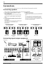
Front and rear panel
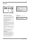
Control panel
■
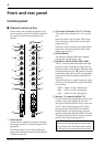
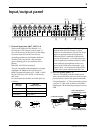
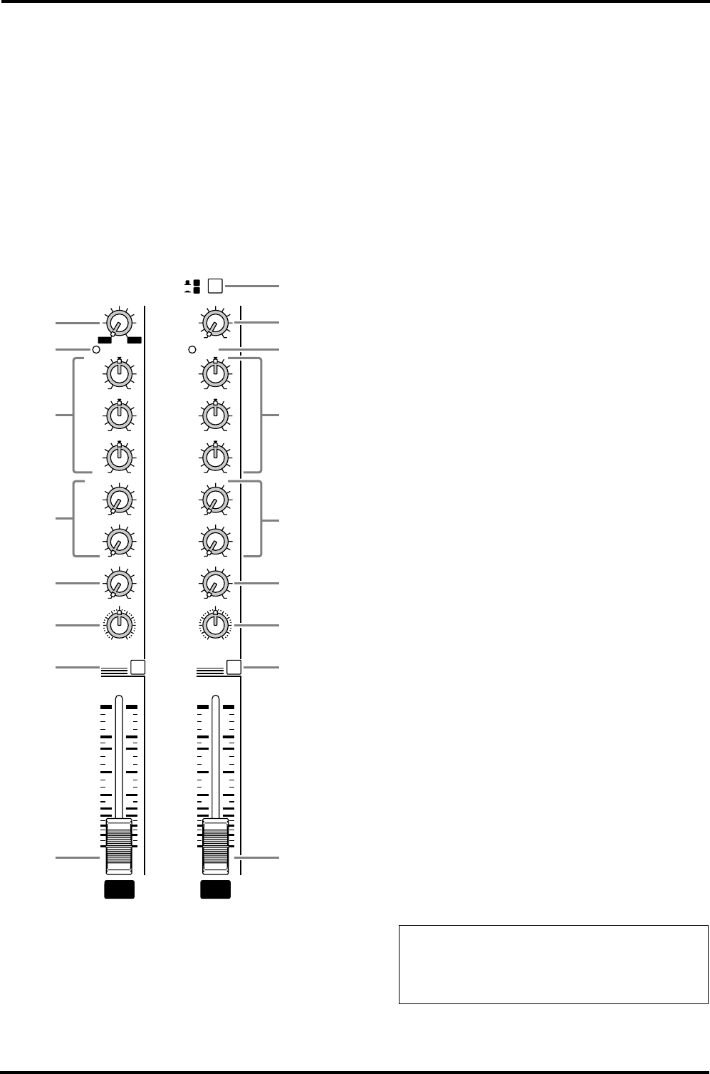
Channel control section
In this section, you can adjust equalization (fre-
quency response), volume level, effect and moni-
tor output levels for the input signal of each
channel.
1
GAIN control
Use this knob to adjust the sensitivity according
to the input signal level, so that the input level is
appropriate.
For the best balance of S/N ratio and dynamic
range, adjust this knob so that the peak indicator
3
lights occasionally.
2
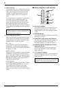
A/B switch (Channels 9/10~11/12 only)
This switch selects channel 9/10~11/12 connec-
tors.
When the switch is up, the signal will be input
from connectors A (phone jacks on the input/
output panel
3
).
When the switch is pressed in, the signal will be
input from connectors B (phono jacks on the
input/output panel
3
).
3
PEAK indicator
The indicator will light 3 dB before clipping,
warning that clipping level is near.
4
Equalizer controls (HIGH, MID, LOW)
This is a 3-band equalizer that adjusts the high
frequency range, mid frequency range, and low
frequency range of each channel. Response is flat
when the knobs are in the “
▼
” position. Rotating
it toward the right will boost the corresponding
frequency band, and rotating it toward the left
will cut it.
The base frequency (or center frequency), range
of boost or cut, and equalizer type of each band
are as follows:
HIGH: 10kHz,
±
15 dB, shelving type
MID: 2.5kHz,
±
15 dB, peaking type
LOW: 100Hz,
±
15 dB, shelving type
5
Monitor 1/2 controls (MONI 1/2)
For each channel, this controls the amount of sig-
nal that is sent to the MONITOR 1/2 buses.
The signal of the MONITOR 1 bus is sent to the
MONI 1 jack (input/output panel
9
). If the
power amp select switch
V
is in the MONI 1-
MONO position, the signal is also sent to the
speakers connected to the SPEAKERS L1/2 jacks.
The signal of the MONITOR 2 bus is sent to the
MONI 2 jack (input/output panel
9
).
–34+10
GAIN
–60
–16
1
PFL
100
MONI 1
100
MONI 2
EFFECT
PAN
100
R
L
+15–15
HIGH
+15–15
MID
+15–15
LOW
0
5
10
15
20
25
30
40
50
∞
PEAK PEAK
9/10
PFL
–34+10
GAIN
100
MONI 1
100
MONI 2
EFFECT
BAL
100
R
L
+15–15
HIGH
+15–15
MID
+15–15
LOW
0
5
10
15
20
25
30
40
50
∞
A
B
1
3
4
5
6
7
9
0
3
4
5
6
8
9
0
1
2
Note:
The signal sent to the MONITOR 1/2
buses does not pass through the channel fader
0
(pre-fader send). This means that it will not
be affected by the setting of the channel fader.