


ST (Stereo) section 9
GA32/12, GA24/12—Owner’s Manual
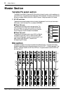
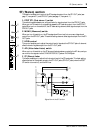
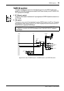
ST (Stereo) section
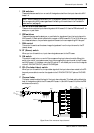
This section enables you to control the ST bus signals output from the ST1 OUT jacks (see
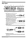
page 17, rear panel
9) and ST2 OUT jacks (see page 17, rear panel J).
A POST ST1 (Post stereo 1) switch
This switch toggles between pre- and post-fader for signals output from the ST2 OUT jacks.
When you turn this switch on, signals that passed the ST fader are output from the ST2 OUT
jacks. When you turn the switch off, the ST fader setting does not affect signals output from the
ST2 OUT jacks.
B MONO (Monaural) switch
When you turn this switch on, the ST bus signals will be mixed into a monaural signal and
output from the ST2 OUT jacks. This switch setting does not affect signals output from the ST1
OUT jacks.
C LEVEL control
This control enables you to adjust the output level of signals at the ST2 OUT jacks. It does not
affect the level of signals output from the ST1 OUT jacks.
D AFL (After-fader Listen) switch
When you turn this switch on, the ST bus post-fader signals are routed to the AFL bus, and you
can monitor the signals via the C-R MONITOR OUT jacks or PHONES jack.
E ST (Stereo) fader
This fader enables you to adjust the final output level of the ST bus signals. This fader setting
affects the level of the signals routed to the ST1 OUT jacks, ST2 OUT jacks (when the POST
ST1 switch is turned on), and the AFL bus.
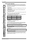
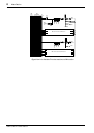
Signal flow in the ST section
AFL
10
5
0
5
10
20
30
40
50
60
MONO
POST ST1
100
LEVEL
ST1
ST2
1
2
3
4
5
ST2
OUT
ST1
OUT
REC
OUT
ST
INSERT
I/O L
ST
INSERT
I/O R
R
L
R
L
R
L
POST
ST1
AFL
LR
AFL
LEVELMONO
RL
ST