


TAPE IN section 13
GA32/12, GA24/12—Owner’s Manual
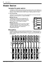
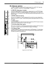
TAPE IN section
This section enables you to control line-level signals input from the TAPE IN jacks. Input
signals from the TAPE IN jacks can be routed to the ST bus or directly to the C-R MONITOR
OUT jacks and PHONES jack.
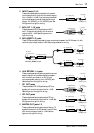
A ST (Stereo) control
This control knob determines the level of input signals at the TAPE IN jacks that are sent to on
the ST buses.
B ON switch
This switch turns on and off the signals sent from the TAPE IN jacks to the ST bus. This switch
setting does not affect signals (input from the TAPE IN jacks) that are monitored via the C-R
MONITOR OUT jacks and PHONES jack.
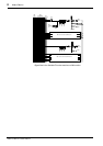
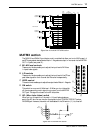
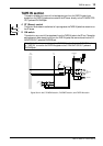
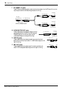
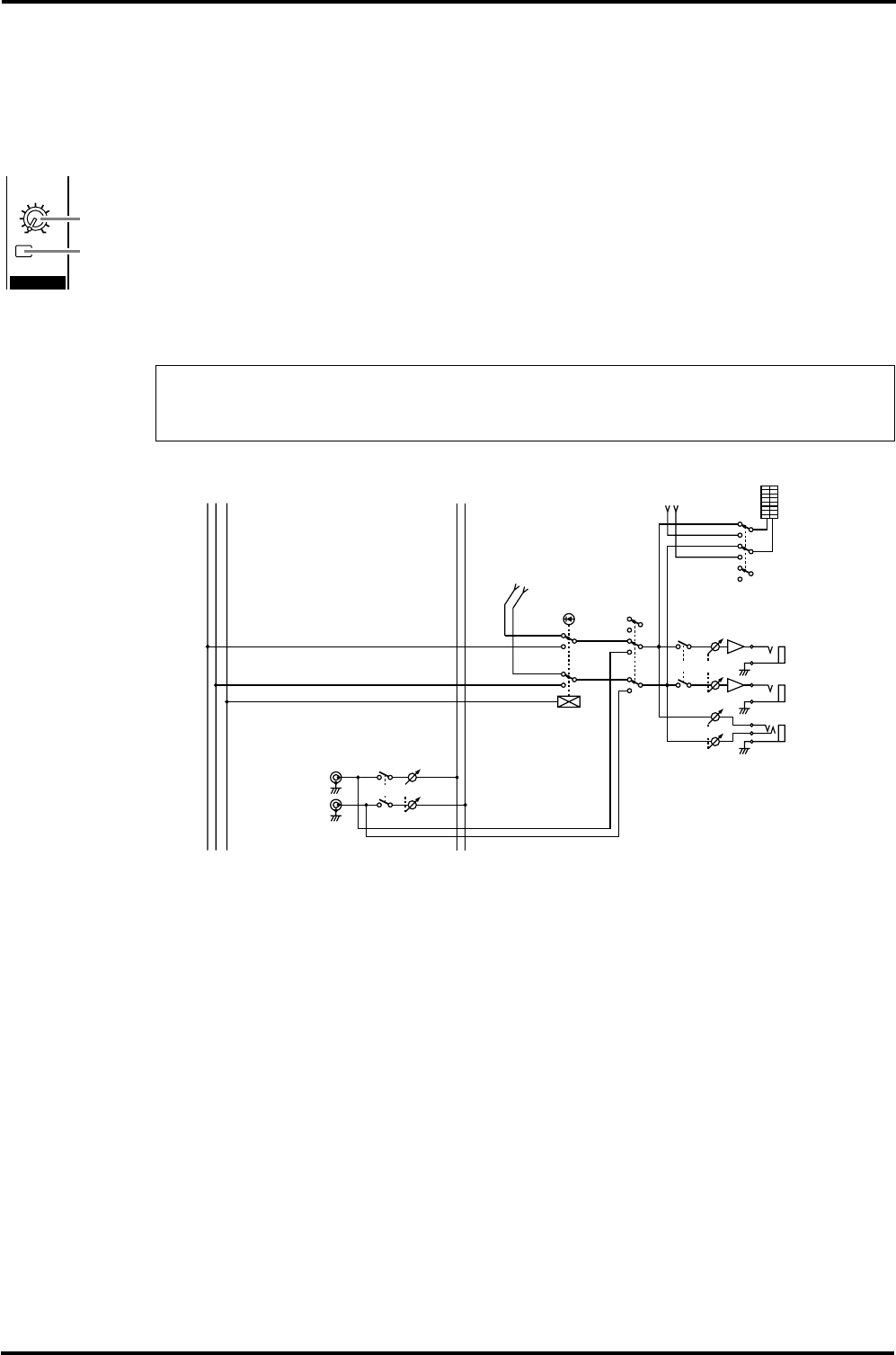
Signal flow in the C-R MONI section, PHONES section, and TAPE IN section
Note: Set the Monitor source select switch (C-R MONI section 1) in the C-R MONI section
to “TAPE IN” to monitor the TAPE IN signals via the C-R MONITOR OUT jacks and
PHONES jack.
TAPE IN
ST
ON
100
2
1
2
TAPE
IN
C-R
MONITOR
OUT
PFL
R
L
TAPE IN
PFL/AFL
PFL
LEVEL
LEVEL
MATRIX
PFL•AFL/TAPE
STON
from AFL
CTLRL
1
from MTRX
ON
PHONES
L
R
RL
ST