


4
Front Panel
GA32/12, GA24/12—Owner’s Manual
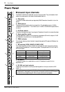
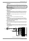
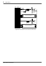
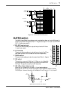
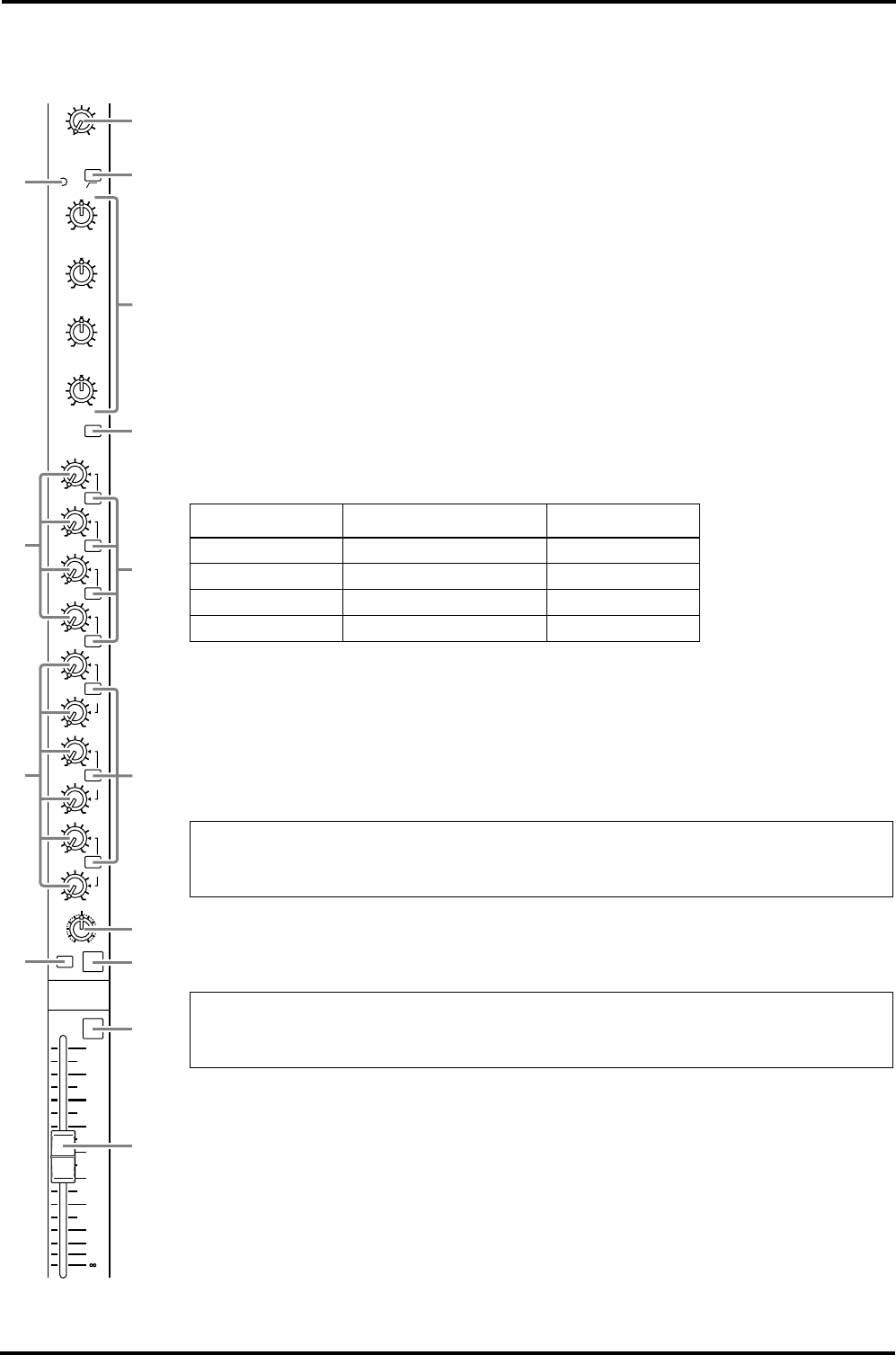
Stereo input channels
The GA32/12 and GA24/12 provide two stereo input channel modules. Use the paired
INPUT 13/14 and 15/16 jacks (see page 17, rear panel
5
) to input stereo signals. If you
connect signals only to the 13L (MONO) jack or 15L (MONO) jack, the same signal will
be sent t the o M1–4 and ST buses.
A
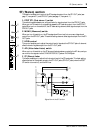
GAIN control
This control is used to adjust input sensitivity. The adjustable range is +10 dB to –34 dB.
B
PEAK indicator
This indicator lights up when the level of signals that have been processed by the EQ
reaches 3 dB below the clipping level.
C
High pass filter switch
This high pass filter is used to cut the frequency range below 80 Hz with a slope of 12 dB/
oct.
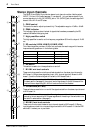
D
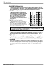
EQ controls (HIGH/HI-MID/LO-MID/LOW)
This 4-band equalizer provides
±
15 dB of cut and boost over each range, with the center
frequencies and types shown in the following table.
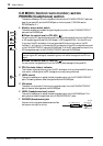
E
EQ switch
This switch is used to turn the equalization on and off.
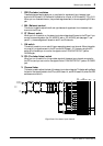
F
M1–M4 mix level controls
These controls are used to route the post fader signals from the stereo input channel to
MIX buses 1–4. When stereo signals are input, the L channel signal will be sent to MIX
buses 1, 3, and the R channel signal will be sent to MIX buses 2 and 4.
G
ON switches (M1–M4)
These switches are used to turn on and off the signals routed from the stereo input channel
to MIX buses 1–4.
H
M5–M10 mix level controls
These control knobs route the stereo input channel signals to MIX buses 5–10. Stereo
input signals are mixed into a monaural signal and sent to MIX buses 5–10. Use the PRE
switches
9
to select pre- or post-fader.
Band Center frequencies Type
HIGH 10 kHz shelving
HI-MID 3 kHz peaking
LO-MID 800 Hz peaking
LOW 100 Hz shelving
Note: When you press down the M1–M4 switches to the FIX position in the Variable/
Fix select section (see page 6), the output level of signals sent to the MIX buses will be
fixed and the corresponding M1–M4 mix level controls will be disabled.
Note: When these switches are set to off, no signals are sent from the stereo input
channel to the corresponding MIX buses regardless of the setting of the switches in the
Variable/Fix select section (see page 6).
+15–15
EQ
ON
PEAK
HIGH
+15–15
HI-MID
+15–15
100
LOW
M1
100
M2
ON
100
M3
ON
100
M4
ON
100
M5
PRE
100
M6
PRE
100
M8
PRE
100
RL
M10
BAL
ON
PFL
ST
100
M9
100
M7
+15–15
LO-MID
–34+10
GAIN
10
5
0
5
10
20
30
40
50
60
3
5
1
2
4
0
B
C
D
A
7
9
6
8
80