


12 Master Section
GA32/12, GA24/12—Owner’s Manual
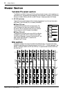
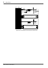
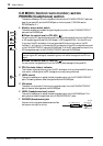
C-R MONI (Control room monitor) section
PHONES (headphones) section
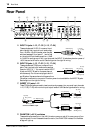
This section enables you to control signals monitored via the C-R MONITOR OUT jacks (see
page 18, rear panel
M) and the PHONES jack on the front panel (C-R MONI section/
PHONES section
6).
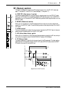
A Monitor source select switch
This switch enables you to select the type of signal to monitor via the C-R MONITOR OUT
jacks and the PHONES jack.
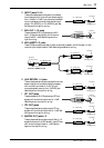
■ When the switch is set to PFL/AFL ( )
You will monitor PFL signals (signals routed from input channels/AUX returns to the PFL bus)
or AFL signals (signals routed from MIX buses 1–10/ST buses/MATRIX 1–2 to the AFL bus).
If any one of the PFL switches for the input channels/AUX returns is turned on, the PFL
indicator
2 will light up. In this case, the PFL bus signals (not the AFL bus signals) are routed
to the C-R MONITOR OUT jacks and PHONES jack. If all the PFL switches are turned off, the
AFL bus signals are sent to the C-R MONITOR OUT jacks and PHONES jack.
■ When the switch is set to TAPE IN ( )
You can monitor the signals input from the TAPE IN jacks (see page 18, rear panel N).
B PFL (Pre-fader Listen) indicator
This indicator lights up when any one of the PFL switches for the input channels/AUX returns
is turned on, indicating that the PFL bus signal is currently being monitored.
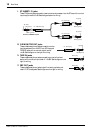
C LEVEL control
This control enables you to adjust the level of signals output from the C-R MONITOR OUT
jacks. This setting does not affect the signal level at the PHONES jack.
D ON switch
This switch turns on and off the monitoring signals output from the C-R MONITOR OUT
jacks. It does not affect signals at the PHONES jack.
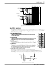
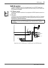
E LEVEL (Headphones level) control
This control enables you to adjust the level of signals output from the PHONES jack. This
setting does not affect the signal level at the C-R MONITOR OUT jacks.
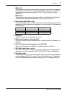
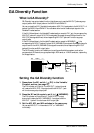
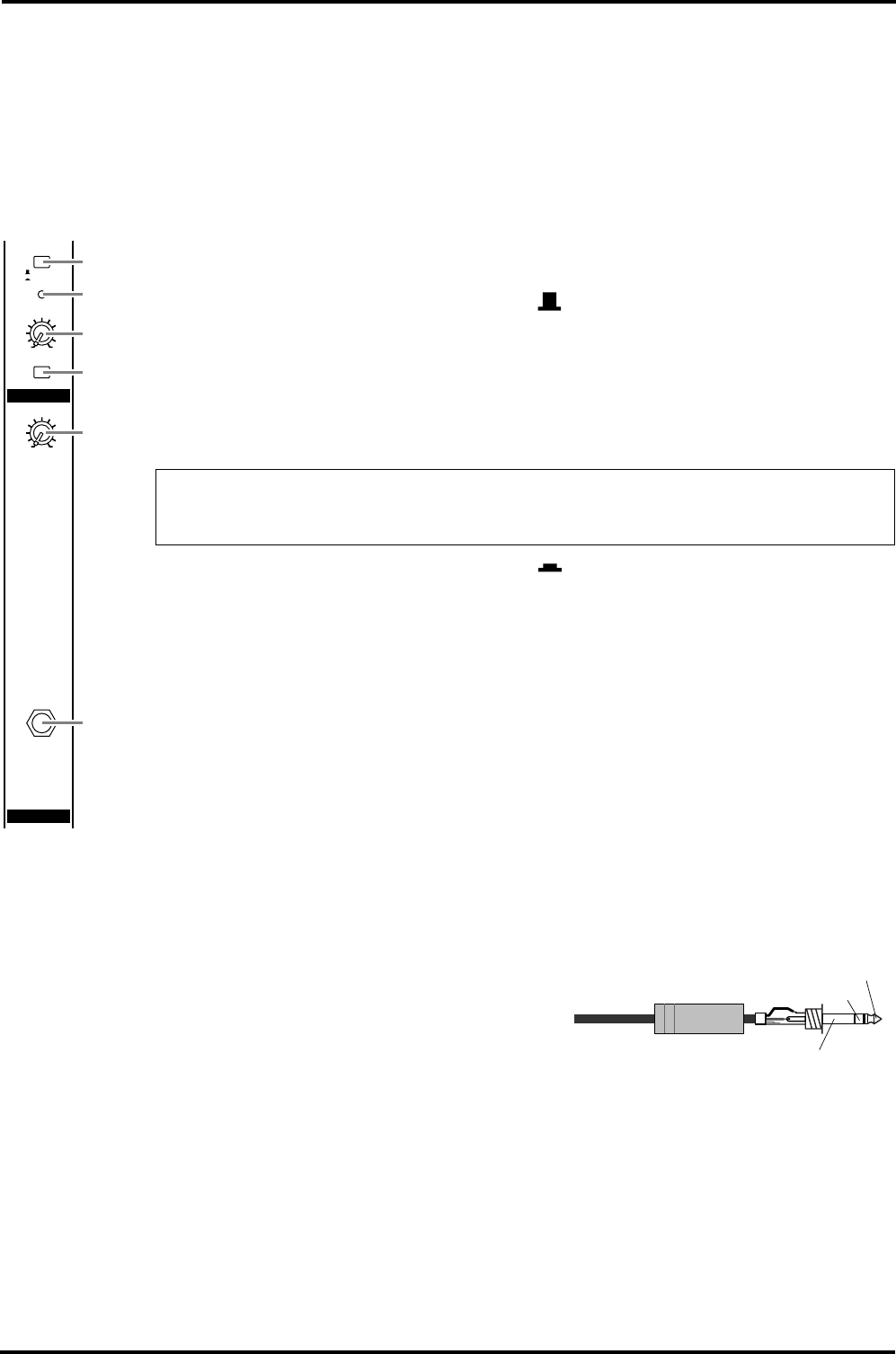
F PHONES (Headphones) jack
Connect monitoring stereo headphones here. See
the figure on the right for wiring.
Note: If you turn on any one of the PFL switches for the input channels/AUX returns while
monitoring the AFL bus signal, the switching circuit will switch the signal to the PFL bus
signal.
C-R MONI
PHONES
ON
PFL
PFL/AFL
TAPE IN
LEVEL
100
LEVEL
100
2
3
5
6
1
4
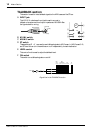
1/4" TRS phone plug
Tip (left)
Ring (right)
Sleeve (ground)