


MATRIX section 11
GA32/12, GA24/12—Owner’s Manual
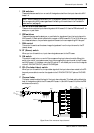
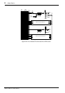
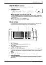
Signal flow in the AUX RETURN section
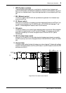
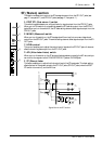
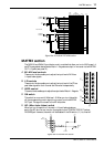
MATRIX section
The GA32/12 and GA24/12 provide two matrix modules that allow you to mix MIX buses 1–4
and ST bus signals at desired levels. Matrix 1–2 signals are output in monaural via the MATRIX
OUT 1–2 jacks (rear panel
K).
A M1–M4 level controls
These control knobs enable you to adjust the input level of MIX bus
1–4 post-fader signals.
B L/R controls
These control knobs enable you to adjust the input level of the ST bus
post-fader signals for the L channel and R channel independently.
C LEVEL control
This control knob enables you to adjust the output level of Matrix 1–2 signals.
D ON switch
This switch turns on and off Matrixes 1–2. When you turn this switch
off, the corresponding matrix signal is not output from the MATRIX
OUT jack. The signal is not sent to the AFL bus, either.
E AFL (After-fader Listen) switch
When you turn this switch on, the matrix 1–2 post-fader signals are
sent to the AFL bus. You can monitor the signals via the C-R MONITOR OUT jacks or
PHONES jack. However, this switch will be disabled if the ON switch (
4) is turned off.
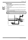
Signal flow in the MATRIX section
AUX RETURN
4R
3R,
4L(MONO)
3L(MONO),
2R
1R,
2L(MONO)
1L(MONO),
ST
ST
L
M10
M9
M8
M7
M6
M5
ON
PFL
PFL
M4
M3
M2
M1
ON
109876512344321
PFL
CTL
RL
ST
MIX
(VARIABLE)
MIX
(FIX)
0
R
0
L
0
M4
0
M3
0
M2
0
M1
LEVEL
AFL
ON
1
100
0
R
0
L
0
M4
0
M3
0
M2
0
M1
LEVEL
AFL
ON
2
100
1
2
4
3
MATRIX
5
1
4
3
from
MIX OUT
MATRIX
OUT
1,2
LEVEL
R
L
AFL
LR
2
AFL
M4
M3
M2
M1
ON
to Meter
RL
ST