


METER SELECT section 15
GA32/12, GA24/12—Owner’s Manual
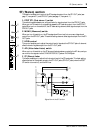
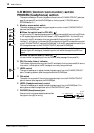
METER SELECT section
You can select the signal source to be displayed in the Meter bridge
section.
A Source select switch
This switch enables you to select the signal source to be displayed on
the MATRIX (PFL•AFL/TAPE) meter (Meter bridge
3) in the right
corner of the level meter.
■ When the switch is set to PFL-AFL/TAPE ( )
The meter indicates either the PFL/AFL bus output level or the input level of the signals sent
from the TAPE IN jacks, depending on the setting of the Monitor source select switch in the
C-R MONI section.
■ When the switch is set to MATRIX ( )
The meter indicates the output level of Matrix 1 and 2.
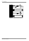
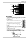
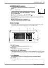
Meter bridge
This peak level meter indicates the output level of the MIX buses, ST bus, Matrixes 1/2, PFL
bus, and AFL bus, and the level of the signal input from the TAPE IN jacks.
A M1–M10 meters
These meters indicate the output level of MIX OUT 1–10.
B ST1 meters
These meters indicate the output level of ST1 OUT.
C MATRIX (PFL•AFL/TAPE) meters
These meters indicate the PFL/AFL bus level, input level of signals sent from the TAPE IN jacks,
or the output level of Matrixes 1/2, depending on the selection made in the METER SELECT
section.
D POWER indicator
When the power to the GA32/12 (or GA24/12) is turned on, this indicator lights up.
E PHANTOM indicator
This indicator lights up when any of the phantom power supplies (see page 16, rear panel 4)
are turned on.
METER SELECT
PFL•AFL/TAPE
MATRIX
1
PEAK
+8
+5
+3
+1
0
–1
–3
–5
–7
–10
–15
–20
PEAK
+8
+5
+3
+1
0
–1
–3
–5
–7
–10
–15
–20
PEAK
+8
+5
+3
+1
0
–1
–3
–5
–7
–10
–15
–20
PHANTOM
POWER
M1 M2 M3 M4 M5 M6 M7 M8 M9 M10 L
ST1 MATRIX
R12
PFL•AFL / TAPE
LR
21 3 4
5