


16 Rear Panel
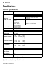
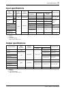
GA32/12, GA24/12—Owner’s Manual
Rear Panel
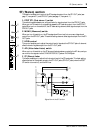
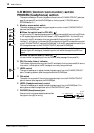
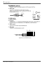
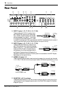
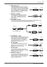
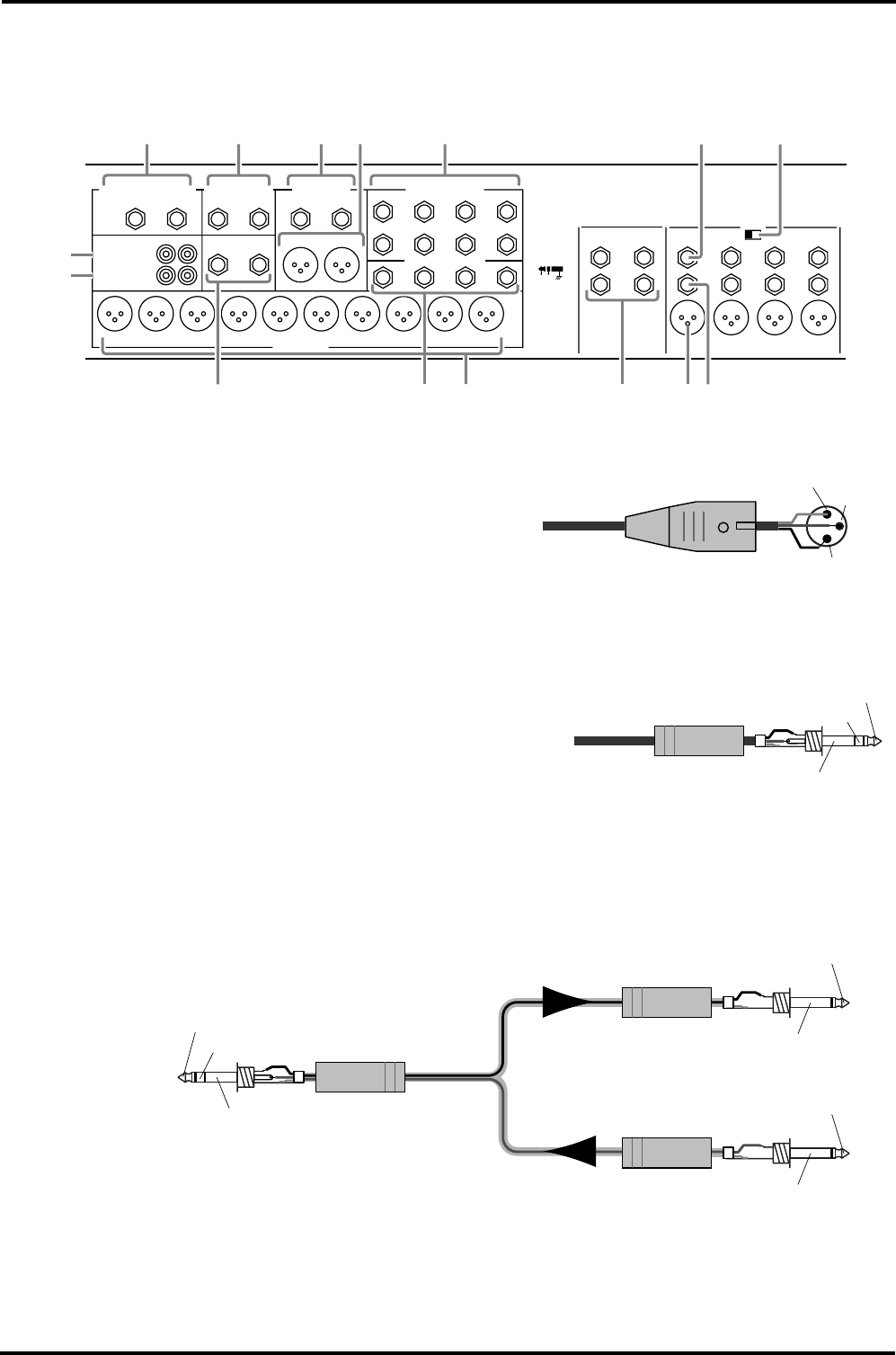
A INPUT A jacks 1–12, 17–32 {1–12, 17–24}
These are balanced, XLR-3-31 monaural input
jacks. Usually their nominal input levels range
from –16 dB to –60 dB. However, when the pad
switches (see page 2, front panel
1) are turned
on, the nominal input levels range from +10 dB
to –34 dB. For every group of four input channels, the INPUT A jacks have phantom power of
+48 V that can be turned on and off. See the figure on the right for wiring.
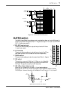
B INPUT B jacks 1–12, 17–32 {1–12, 17–24}
These are balanced TRS phone, monaural input
jacks. Their nominal input levels are the same as
those for INPUT A
1. You cannot use the INPUT
A jack and INPUT B jack for the same channel
simultaneously. Do not connect plugs to both A
and B jacks of the same channel at the same time.
Otherwise, a malfunction may occur. Phantom power is not available for the INPUT B jacks.
See the figure on the right for wiring.
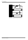
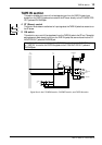
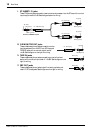
C INSERT I/O jacks 1–12
These TRS phone jacks are used to insert an external processor into monaural input channels
1–12, 17–32 {17–24} with nominal input/output levels of 0 dB. See the figure below for wiring.
D PHANTOM (+48 V) switches
These switches are used to turn the +48 V phantom power on and off for every group of four
input channels. If one of these switches is turned on, the PHANTOM indicator on the Meter
bridge will light up.
4L (MONO) 3L (MONO) 2L (MONO) 1L (MONO)
12
BBBB
INSERT I/O
0dB
11
INSERT I/O
0dB
10
INSERT I/O
0dB
9
INSERT I/O
0dB
INPUT16R 14R
15L
(MONO) 13L (MONO)
INPUT INPUT INPUT
AAAA
INPUT INPUT INPUT INPUT
PHANTOM (+48V)
OFF ON
INSERT I/O
OUT IN
2345678910 1
MIX OUT +4dB
C-R MONITOR OUT +4dB MATRIX OUT +4dB
ST INSERT I/O 0dB
ST2 OUT +4dB AUX RETURN +4dB
MIX INSERT I/O 0dB
ST1 OUT +4dB
TAPE IN –10dBV
REC OUT –10dBV
4R 3R 2R 1R
4
RLR
RL
L2 1
RL
RL
321
5
80AC9
1B 2
3 4
D
E
76
Male XLR plug
1 (ground)
3 (cold)
2 (hot)
1/4" TRS phone plug
Tip (hot)
Ring (cold)
Sleeve (ground)
1/4" phone plug
1/4" phone plug
1/4" TRS phone plug
To processor’s input
From processor’s output
Connect to INSERT I/O jack
Tip (send)
Tip (send)
Ring (return)
Sleeve (ground)
Sleeve (ground)
Tip (return)
Sleeve (ground)