


Master Section
5
MD4—Owner’s Manual
Master Section
1
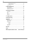
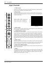
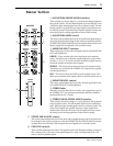
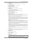
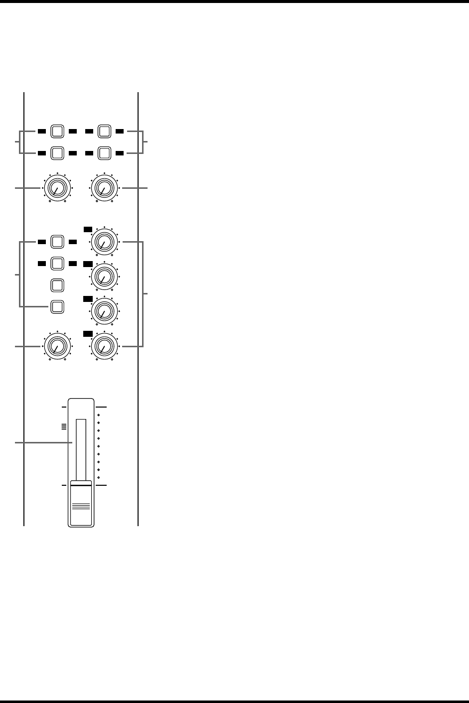
AUX RETURN GROUP ASSIGN switches
These switches are used to assign (i.e., send) the Aux Return signals to
the recorder’s tracks. The left-channel signal is sent to odd buses 1 and
3. While the right-channel signal is sent to even buses 2 and 4. The Aux
Return signals are typically the processed signals returned from a ste-
reo effects processor. Note that the Aux Return signals are always sent
to the Stereo bus for mixing regardless of these switch settings.
2
AUX RETURN LEVEL control
This rotary control adjusts the level of the Aux Return signals that are
sent to the Stereo bus for mixing. It’s also used in conjunction with the
AUX RETURN GROUP ASSIGN switches to adjust the level of the Aux
Return signals that are assigned to the recorder’s tracks.
3
MONITOR SELECT switches
These switches are used to select the signal source for the MONITOR
OUT and headphones.
GROUP
—These switches select the Group buses as the monitor
source. This allows you to monitor signals assigned to tracks. When
only the [1–3] or [2–4] switch is pressed, the monitor signal is mono.
Press both switches to monitor stereo signals.
STEREO
—This switch selects the Stereo bus as the monitor source.
This allows you to monitor the STEREO OUT signal and is typically
used during mixdown.
CUE
—This switch selects the CUE bus as the monitor source. This
allows you to monitor track signals, which is useful for punch in/out.
4
MONITOR LEVEL control
This rotary control adjusts the level of the monitor signal that is sent
to the MONITOR OUT and headphones.
5
STEREO fader
This fader is used to adjust the level of the stereo signal that is sent to
the STEREO OUT. For optimum performance this fader should be
positioned about the 7–8 mark.
6
STEREO SUB IN GROUP ASSIGN switches
These switches are used to assign (i.e., send) the Stereo Sub In signals
to the recorder’s tracks. The left-channel signal is sent to odd buses 1
and 3. While the right-channel signal is sent to even buses 2 and 4. The
Stereo Sub In signals are typically the stereo output signals from
another mixer. Note that the Stereo Sub In signals are always sent to
the Stereo bus for mixing regardless of these switch settings.
7
STEREO SUB IN LEVEL control
This rotary control adjusts the level of the Stereo Sub In signals that are sent to the Stereo bus
for mixing. It’s also used in conjunction with the STEREO SUB IN GROUP ASSIGN switches
to adjust the level of the Stereo Sub In signals that are assigned to the recorder’s tracks.
8
CUE LEVEL controls
These controls adjust the level of the CUE signal for each track. During recording, or when no
disc is inserted, the CUE source is the signal assigned to a track. During playback, the CUE
source is the disc playback signal.
1 2 1 2
3 4 3 4
LEVEL
010
MONITOR LEVEL
MIN MAX
LEVEL
010
GROUP ASSIGN
1 3
2 4
GROUP
STEREO
CUE
GROUP ASSIGN
1
2
3
4
010
010
010
010
10
9
8
7
6
5
4
3
2
1
0
MASTER
AUX
RETURN
STEREO
SUB IN
STEREO
MONITOR
SELECT
CUE LEVEL
4
2 7
1
3
5
6
8