


MGP16X/MGP12X Owner’s Manual
17
Controls and Connectors
Where Your Signal Goes Once It’s Inside the Box
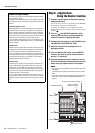
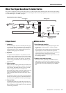
The purpose of configuring an audio system around a mixer is to collect signals from all channels and mix their levels and other settings
to achieve a good balance. The following simplified mixer block diagram shows how the input signal flows once it’s inside the mixer. For
an overall block diagram of the MGP, see page 33.
Input channel
q Head amp
The very first stage in any mixer, and usually the only stage
with significant “gain” or “amplification.” The head amp has
a “gain” control that adjusts the mixer’s input sensitivity to
match the level of the source. Small signals (e.g. mics) are
amplified, and large signals are attenuated.
w Equalizer
An equalizer boosts (amplifies) or cuts (attenuates) certain
frequency ranges to shape the tone. It can be used to modify
the tone to suit the acoustic characteristics of a room, to make
creative sounds, or for many other purposes. An equalizer
could be a high pass filter that cuts the sound below a speci-
fied frequency.
e PEAK indicator
When the level of an input signal exceeds the level that can be
handled by the mixer’s head amp or equalizer, distortion and
noise will result. The PEAK indicators are used to visually
check the signal level to ensure no overload occurs.
If the PEAK indicator lights continuously, make sure that sig-
nals are not amplified too much by the equalizer, and if
needed, adjust the GAIN control of the head amp to reduce
the level.
It is important to know the mixer stage for which the PEAK
indicators are indicating signal levels. The PEAK indicator of
this unit detects the signal after the head amp and EQ stage.
r Channel fader
A channel fader enables you to adjust the level of the corre-
sponding input channel signal that is going to be routed to the
buses (excluding a pre-fader signal). It is the most often used
control during performance.
Master section
t Bus (Summing Amplifier)
This is where the actual “mixing” takes place. Signals from
all of the mixer’s input channels are “summed” (mixed)
together here.
The signals flow in each channel from top to down after being
adjusted by the level control, and then these signals are
summed (mixed) from left to right. Finally, the overall level is
adjusted by the master control located at far right.
The operation of summing from left to right is the role of the
bus (summing amplifier).
y Master control and level meter
The master controls, specifically, the STEREO fader and
GROUP faders, are the means used to adjust the level of all
signals from all of the mixer’s input channels. The level meter
LED shows the level of the signal flowing to the STEREO
bus.
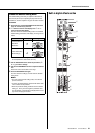
Simplified Mixer Block Diagram
Input channel Master section
INPUT
HA
EQ
PEAK
CH Fader
SUM
GROUP
Fader
STEREO
Fader
LED meter
OUTPUT
CHs INPUT
q Head amp w Equalizer e PEAK
indicator
r Channel
fader
t Bus y Master control and
level meter