


MGP16X/MGP12X Owner’s Manual
25
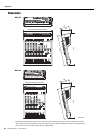
Controls and Connectors
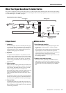
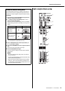
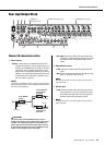
Rear Input/Output Block
Channel I/O connectors section
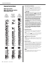
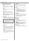
q Mono inputs
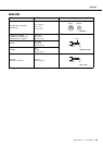
• INSERT: These jacks are located between the com-
pressor and equalizer of the corresponding input
channel. The INSERT jacks are ideal for connect-
ing devices such as graphic equalizers or noise
filters into the corresponding channels. These are
TRS (tip, ring, sleeve) phone jacks that carry both
the send and return signal (tip = send/out; ring =
return/in; sleeve = ground).
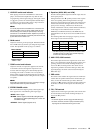
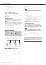
NOTE
Connection to an INSERT I/O jack requires a special insertion
cable as illustrated below. Use a separately-sold Yamaha inser-
tion cable (YIC025/050/070).
CAUTION
The signal output from the INSERT jacks is reverse-
phased. This should not be a problem when connecting to
an effect unit, but please be aware of the possibility of
phase conflict when connecting to other types of device.
A reversed-phased signal may result in degraded sound
quality or even complete sound cancellation.
• MIC/LINE: These are combo jacks that support both
XLR-type and TRS phone-type plugs, and are for
connection of both microphones and/or instru-
ments.
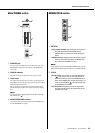
w Mono/Stereo inputs
• LINE: These are unbalanced phone-jack stereo line
inputs.
• MIC: These are balanced XLR-type microphone input
jacks. (1: Ground; 2: Hot; 3: Cold)
NOTE
On any given channel, you may use either an XLR or phone
jack, but not both.
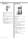
e Stereo input
• LINE: These are stereo input jacks that connect line-
level instruments, such as a synthesizer. These
are unbalanced input jacks. Two jack types are
provided: phone type and RCA pin type.
NOTE
On any given channel, you may use either a phone or RCA
jack, but not both.
y!1 t r e w q
ui!0
!2
o
(MGP12X:
CHs 9/10, 11/12)
(MGP12X: CHs 5/6, 7/8) (MGP12X: CHs 1 to 4)
To the INSERT
I/O jack
Sleeve (ground)
Ring: IN
Tip: OUT
To the input jack
of the external
processor
To the output jack
of the external
processor
Tip: OUT
Tip: IN