


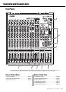

Controls and Connectors
MGP16X/MGP12X Owner’s Manual
20
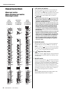
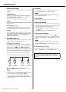
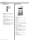
!3 PAN control
PAN/BAL control
BAL control
The PAN control knob determines the stereo positioning of
each mono channel signal in the GROUP 1-2, 3-4 buses or in
the stereo L and R buses. For example, rotating the knob
toward L moves the sound to the left (depending on the loca-
tion of the knob).
The BAL control knob sets the balance between left and right
stereo channels. For example, rotate the knob toward L to
increase the volume level of the left or Groups 1 and 3, and
decrease the level of the right or Groups 2 and 4.
!4 ON switch
Turn this switch on ( ) to send the respective channel’s
signal to the buses. The switch lights when on.
!5 Input Meter
The LEDs indicate the input channel’s post-equalizer signal
level. The SIG indicator lights when a signal is being input
into the channel. The PEAK indicator lights when the input
signal level is 3dB below clipping.
!6 Bus assign switches
These switches determine the bus(es) to which each channel’s
signal is sent. Press the switch in ( ) to output the signal to
the corresponding buses.
• 1-2, 3-4 switches: Assign the channel’s signal to the
GROUP1-2, 3-4 buses.
• ST switch: Assigns the channel’s signal to the STE-
REO L and R buses.
NOTE
To send the signal to each bus, engage the ON switch.
!7 PFL switch and indicator
When the PFL (Pre-Fader Listen) switch is on ( ), the
indicator will light and the channel pre-fader signal is output
to the MONITOR OUT and PHONES jacks for monitoring.
!8 Channel fader
Adjusts the level of the channel signal. Use these controls to
adjust the balance between the various channels.
NOTE
To reduce noise, set the fader sliders for any unused channels
all the way down.
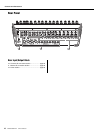
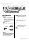
Master Control Block
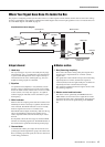
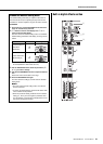
iPod/iPhone section
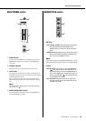
q USB connector and indicator
This is a USB port dedicated for iPod/iPhone use. Using the
USB cable that came with the iPod/iPhone, connect the iPod/
iPhone. The indicator lights when the mixer recognizes the
iPod/iPhone.
If the mixer does not recognize the device or if a non-compli-
ant iPod/iPhone is connected, the indicator remains off.
For details on supported iPod/iPhone models, see “Supported
iPod/iPhone models” on page 30.
CAUTION
• Use the genuine Apple Dock Connector USB Cable for
the iPod/iPhone connection.
• Connect the USB connector to the iPod/iPhone before
turning the mixer power on.
• When connecting to an iPod/iPhone, allow at least 6 sec-
onds to pass between turning the mixer on and off and
plugging or unplugging the USB cable.
• Please do not use a USB hub.
• The mixer’s USB port is dedicated for iPod/iPhone use
only. Please do not connect other USB devices.
NOTE
• While the indicator lights, the iPod/iPhone is charged.
• If you connect your iPhone, an incoming call cause a ringing
sound to be output. In order to prevent this, we recommend
that your iPhone’s “Airplane” mode be turned on.
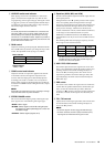
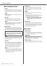
w Routing assign switches
Determine the destination of the input signal. The switch set-
ting and the destination is shown below.
NOTE
• The volume of an iPod/iPhone which was assigned to CH15/
16 (CH11/12) cannot be controlled by the GAIN control.
• Use the detailed setting mode in the column on the next
page to attenuate the playback level from an iPod/iPhone
assigned to CH15/16 (CH11/12).
Switch
Switch
Setting
Audio Signal
Input Source
Output Destina-
tion Channels
TO CH15/16
(MGP16X)
TO CH11/12
(MGP12X)
ANALOG
CH15/16 jacks
(MGP16X)
CH11/12 jacks
(MGP12X)
CH15/16
(MGP16X)
Ch11/12
(MGP12X)
USB
iPod/iPhone
TO 2TR IN
ANALOG
2TR IN jacks
2TR IN
USB
iPod/iPhone
qw