


MGP16X/MGP12X Owner’s Manual
19
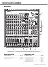
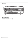
Controls and Connectors
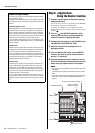
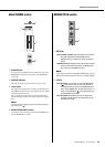
t LEVELER switch and indicator
When playing music from an iPod/iPhone or other audio
players, the actual sound output level may differ for each
song depending on the assigned category. Turning this switch
on ( ) lets you have the volume adjusted automatically to
a certain level, preventing sudden jumps or dips in the level.
The indicator lights when it is turned on.
NOTE
If an audio player other than iPod/iPhone is connected to the
input jacks (LINE) on the rear panel, initially adjust the input
level according to the softest part (lowest level) of the song,
and then turn on the LEVELER switch. Adjust the input level so
that the level meter indication occasionally rises above the “<”
(0) level while the PFL switch is on.
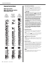
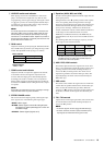
y GAIN control
Adjusts the sensitivity of the input signal. Monaural channels
have a 26dB switch (w) that lets you change the range of this
control. The adjustable sensitivity range is as follows.
Mono channel
Stereo channel
-34dB to +10dB
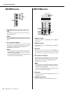
u COMP control and indicator
Adjusts the amount of compression applied to the channel.
As the knob is turned to the right the compression ratio
increases while the output gain is automatically adjusted
accordingly. The result is smoother, more even dynamics
because louder signals are attenuated while the overall level
is boosted. The COMP indicator will light when the compres-
sor operates.
NOTE
Avoid setting the compression too high, as the higher average
output level that results may lead to feedback.
i STEREO IMAGE switch
This switch selects the output signal by switching the input
stereo signal to one of the following three signal types.
• MONO : Mono signal
• BLEND : Stereo signal in which left and right inputs
are mixed in a certain percentage for a more nat-
ural stereo image.
• STEREO : Stereo signal (original, as is)
o Equalizer (HIGH, MID, and LOW)
This three-band equalizer adjusts the channel’s high, mid, and
low frequency bands.
Setting the knob to the “t” position produces a flat response
in the corresponding band. Turning the knob to the right
boosts the corresponding frequency band, while turning to the
left attenuates the band. The upper knob sets the center fre-
quency for the mid range, while the lower knob sets the
amount of attenuation or boost (counterclockwise/clockwise)
for the range. For the CH9/10 and CH11/12 (on the
MGP16X), and CH5/6 and CH7/8 (on the MGP12X), the
attenuation/boost can only be set at a fixed 2.5kHz center fre-
quency.
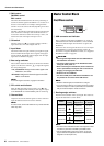
The following table shows the EQ type, frequency, and cut/
boost range for each of the three bands.
* The MID frequency can be adjusted from 250Hz to 5kHz.
The MID frequency is 2.5kHz when the MID frequency
control is set at the center position.
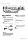
!0 AUX1 PRE, AUX2 controls
These knobs adjust the channel’s signal levels sent to AUX
buses 1 and 2. Each knob controls the signal sent to the corre-
sponding AUX bus. These knobs should generally be set
close to the “t” (nominal) position. The AUX1 control
adjusts the signal before the channel fader (pre-fader). The
signal adjusted by the AUX2 control is determined by the
PRE switch (!1).
!1 PRE switch
This switch selects whether the signal sent to the AUX 2 bus
is taken after the equalizer but before the channel fader (pre-
fader), or after the channel fader (post-fader). When the
switch is on ( ), the mixer sends the pre-fader signal to the
AUX2 bus, so that the AUX2 output is not affected by the
fader.
!2 FX1, FX2 controls
Adjusts the level of the signal (post-fader) sent from the chan-
nel into the FX bus. These knobs should generally be set
close to the “t” position.
NOTE
• To send the signal to the bus engage the ON switch (!4).
• On stereo channels, the LINE L (odd) and LINE R (even)
input signals are mixed before moving into the bus.
26dB switch Range
ON -34dB to +10dB
OFF -60dB to -16dB
Band Type Frequency
Cut/Boost
range
HIGH Shelving 8kHz
±15dBMID Peaking 2.5kHz*
LOW Shelving 125Hz