


MV12/6 — Owner’s Manual
2 MV12/6
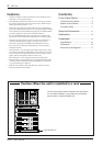
Features
• The MV12/6 offers 12 input channels that can be mixed into stereo,
monaural, or to four group outputs.
• A MONITOR jack offers easy connection to a sub amp for monitor-
ing. It allows monitoring of the main stereo output, TAPE IN input
and the signals from groups 1-2, 3-4.
• The mixer is equipped with a highly efficient, built-in digital effects
section. The built-in effects allow you to create professional sounding
mixes without the need of additional equipment. An EFFECT SEND
jack is also supplied to allow the use of external effectors.
• Two AUX SEND/RETURN jacks are provided. Two separate AUX
buses can be used as sends for external effectors or a monitor system.
• The mixer supplies phantom power to provide easy connection of
condenser microphones that require an external power source.
• The mixer is equipped with INSERT IN, INSERT OUT jacks for
input channels 1-4 allowing individual effects to be inserted into
individual channels.
• Input Channels 1-8 are equipped with XLR type input jacks. A three-
way selector switch allows compatibility with a wide range of sources
such as condenser microphones that need an external power source,
regular dynamic microphones, line level devices, etc.
Input Channels 9-12 are equipped with stereo line input jacks
• The main input and output jacks are also equipped with Euro-block
connectors. These connectors facilitate the installation of the mixer
as a permanent fixture in halls, etc.
• TAPE IN jacks and REC OUT jacks offer easy connection of tape
decks for playback and recording.
Contents
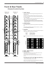
Front & Rear Panels ............................ 3
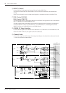
Channel Control Section ........................ 3
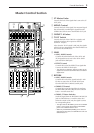
Master Control Section .......................... 5
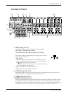
Connector Panel .................................... 7
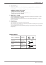
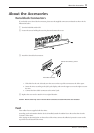
About the Accessories ...................... 11
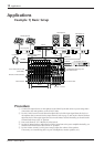
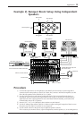
Applications .......................................... 12
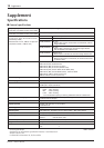
Supplement .......................................... 14
Specifications ....................................... 14
Dimensions .......................................... 16
Block and Level Diagrams.................... 17
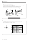
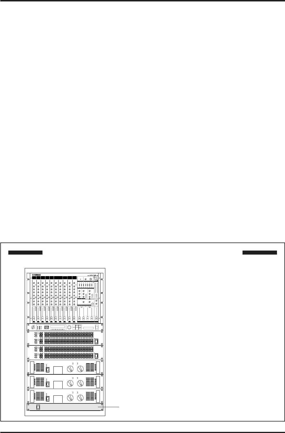
Caution: When the unit is installed in a rack
The main unit’s power switch is located on the rear panel of
the unit. When installed in a rack, please use the external
power switch on a power distributor, etc.
Power distributor, etc.