


MV12/6 — Owner’s Manual
Front & Rear Panels 7
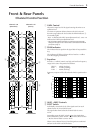
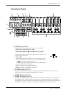
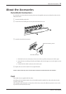
q INPUT Jacks (CH 1-8)
Both balanced XLR type and Euro-block connectors are supplied.
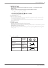
• XLR Type (1:Ground, 2:Hot, 3:Cold)
• Euro-block connectors ( : Hot, : Cold, G: Ground)
Use Input Select Switch to match the input to the type of mic or device
connected to the INPUT jack.
• MIC (+48V)
Allows the connection of condenser mics, etc. Phantom power (DC
+48V) is supplied to the No. 2 and No. 3 pins of the XLR jack and to
the / pins on the Euro-block connector.
* When phantom power is not used, make sure that the Input Select Switch is
set to any position other than MIC (+48V).
• MIC: Compatible with 50-600Ω microphones.
• LINE: Compatible with 600Ω line level devices.
w ST INPUT Jacks (CH 9-12)
Both unbalanced RCA phono type stereo line input jacks and unbalanced Euro-block connectors are
supplied. Both types are compatible with 600Ω line level devices.
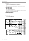
e INSERT IN Jacks (CH 1-4)
r INSERT OUT Jacks (CH 1-4)
These are input/output jacks that are positioned between the equalizer and fader of the Input Channel.
The INSERT IN jacks are balanced phone type jacks with a nominal input/impedance of 0dB/600Ω.
The INSERT OUT jacks are impedance balanced phone type jacks with a nominal output/impedance of
0dB/10kΩ. These jacks can be used to connect a graphic equalizer, compressor, noise filter, etc.
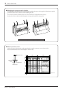
Connector Panel
w qo!1!2!0
werty ui
o
!0
!1
!3