


MV12/6 — Owner’s Manual
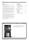
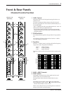
6 Front & Rear Panels
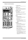
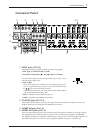
u DIGITAL EFFECT
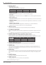
• PROGRAM Select Switch
Selects a program from the built-in digital effects.
VOCAL ECHO 1
VOCAL ECHO 2
VOCAL ECHO 3
VOCAL ECHO 4
VOCAL REVERB 1
VOCAL REVERB 2
VOCAL REVERB 3
VOCAL REVERB 4
• PARAMETER Control
Controls parameters (effect level, speed, etc.) of the selected effect program.
• ON Switch
Switches the built-in digital effect ON (>) or OFF (?). When set to OFF, the signal from the built-in
effect is not sent.
• AUX1, AUX2 Control
Controls the level of the signal that is sent from the built-in digital effects to the AUX1 and AUX2 buses.
• GROUP/ST Control
Controls the level of the signal that is sent from the built-in digital effects to GROUP buses 1-4 and the
STEREO bus.
• GROUP, ST Select Switches
Sends the signal from the built-in digital effects to GROUP buses 1-4 and the STEREO bus.
When the switch is ON (>), the signal is sent to its corresponding buses.
i TAPE IN Control
Controls the level of the signal that is sent from the TAPE IN jack to the STEREO bus.
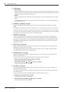
o ST GRAPHIC EQUALIZER
A stereo 7-band graphic equalizer that offers tone adjustment to the signal that is output to the ST OUT
jacks.
A +/-12dB boost or cut is provided at each of the frequency bands 125, 250, 500, 1k, 2k, 4k and 8kHz.
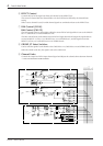
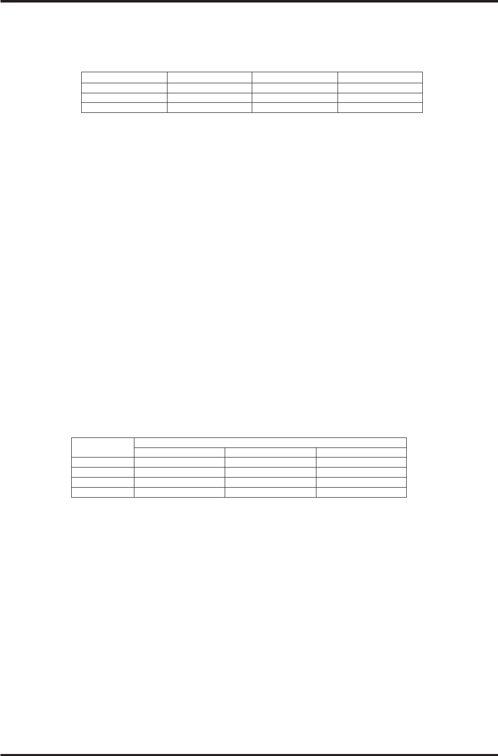
!0 PHONES/MONITOR Output and Meter Select Switch
Selects the signal that is sent to the MONITOR jack, PHONES jack and the level meter.
The three switches are used in combination to select TAPE IN, ST, GROUP 1-2 and GROUP 3-4 signals.
HALL 1
HALL 2
HALL 3
ROOM
PLATE 1
PLATE 2
PLATE 3
GATE REVERB
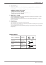
Signal
Switch
? 1-2 > 3-4 ? ST > GROUP ? > TAPE IN
TAPE IN N/A N/A > TAPE IN
ST N/A ? ST ?
GROUP 1-2 ? 1-2 > GROUP ?
GROUP 3-4 > 3-4 > GROUP ?
!1 PHONES/MONITOR Control
Controls the level of the signal that is sent to the MONITOR jack and PHONES jack.
!2 PHONES Jack
This is a stereo phone type jack for connecting a pair of headphones (nominal output/impedance of
3mW/40Ω). Use the !0 PHONES/MONITOR output and meter select switch to select the source to be
monitored with the headphones.
!3 LEVEL Meter
The LEDs indicate the output level of the signal selected with the PHONES/MONITOR output and Meter
Select Switch !0. “0” indicates a nominal level, and the PEAK indicator will light when clipping is immi-
nent.
!4 POWER Indicator
The indicator will light when the main unit’s power is ON.
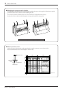
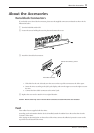
!5 LAMP Connector
A XLR type lamp (AC or DC12V, 0.5A Max) can be attached here.
Refer to the Block Diagram on page 17.