


12 Front and rear panel
—Owner’s Manual
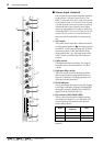
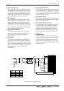
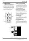
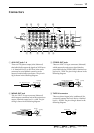
■ STEREO/MONO section
This section separately controls the STEREO
OUT jacks (page 17, 3 in the connector section)
which are the main output of the mixer, and the
MONO OUT jack (page 17, 2 in the connector
section) which outputs a monaural mix of the
STEREO OUT output.
1 MONO (monaural) control
This adjusts the signal level that is sent to the
MONO OUT jack. The level is nominal when the
control is at the “√” position.
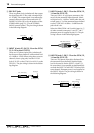
2 POST switch
This switches the output of the fader between the
pre- and post-fader signals. When this switch is
pressed in, the signal after passing through the
STEREO fader (post-fader) will be sent to the
MONO OUT jack. When this switch is in the
upward position, the signal before passing
through the STEREO fader (pre-fader) will be
sent to the MONO OUT jack.
3 STEREO fader
This adjusts the level of the signal that is sent to
the STEREO OUT jack. The position of the STE-
REO fader will affect the signals that are sent
from the ST bus to the STEREO OUT jacks, the
MONO OUT jack (if the POST switch 2 is on),
and the PFL/AFL bus.
4 AFL (after-fader listen) switch
This switch sends the signal of the ST bus to the
PFL/AFL bus. When the switch is on, the signal
following the STEREO fader (the same signal as
output from the STEREO OUT jacks) can be
monitored from the C-R OUT jacks and the
PHONES jack.
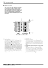
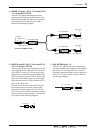
STEREO/MONO section signal flow
AFL
POST
MONO
10
5
0
5
10
15
20
30
40
STEREO
010
1
2
3
4
REC OUT
L
R
MONOPOST
STEREO
OUT
MONO
OUT
AFL
R
PFL/AFL
LR
L
PA D
I/O R
I/O L
ST
ST
INSERT
INSERT
ST
RL
to Meter
to Meter