


6
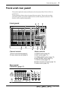
Front and rear panel
—Owner’s Manual
Channel controls
■
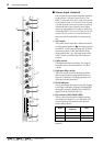
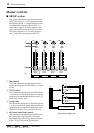
Mono input channels
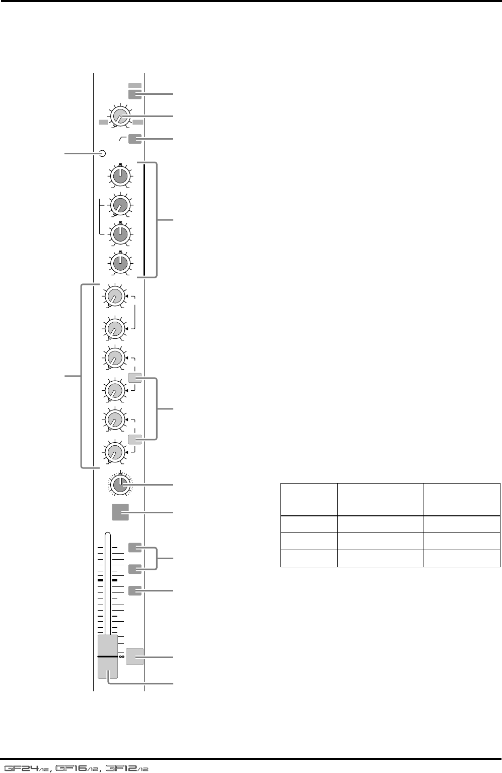
Here are the 20 {12, 8} mono input channels of
the GF24/12 {GF16/12, GF12/12}. The input
channel section processes the signal from the
input jacks of the connector section, and sends
the result to the GROUP buses, AUX buses, and
the ST bus.
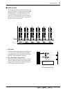
1
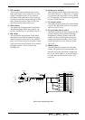
Pad switch
This attenuates the input signal by 26 dB. The
pad is on when this switch is pressed in.
2
GAIN control
This adjusts the input sensitivity. The range of
levels that can be accommodated is –16 dB to
–60 dB when the pad switch (
1
) is off, and
+10 dB to –34 dB when the pad switch is on.
3
High pass filter switch
This is an on/off switch for the high pass filter
that cuts the frequency range below 80 Hz at a
slope of 12 dB/octave. The high pass filter is on
when the switch is pressed in.
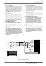
4
PEAK indicator
This is an indicator that detects post-EQ clipping.
It will light 3 dB before clipping, indicating that
the signal is near the clipping level. If this LED
lights, lower the GAIN control (
2
).
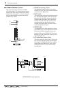
5
EQ controls (HIGH/MID/LOW)
This is a three-band equalizer that boosts/cuts
each frequency band over a
±
15 dB range. The
center frequency and equalizer type for each
band is shown below.
The response is flat when the knob is in the “
▼
”
position.
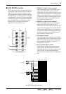
6
AUX controls (1–6)
These knobs adjust the level at which the input
channel signal is sent to the AUX buses 1–6. AUX
controls 1 and 2 are fixed at pre-fader, and AUX
controls 3–6 can be switched between pre/post
fader using the PRE switch (
7
). When a knob is
in the “
√
” position, the level is “nominal”.
PFL
1–2
ON
3–4
ST
10
5
0
5
10
15
20
30
40
HIGH
MID
PEAK
–15 +15
GAIN
–16
+10
–60
26dB
–34
80
PAN
R
EVEN
L
ODD
PRE
PRE
1
2
3
4
5
6
010
010
010
010
010
010
–15 +15
LOW
AUX
PRE
–15 +15
250 5K
4
1
A
8
9
B
2
3
5
7
0
6
C
Band
Center
frequency
Type
HIGH 10 kHz shelving
MID 250 Hz–5 kHz peaking
LOW 100 Hz shelving