


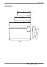
20 Front and rear panel
—Owner’s Manual
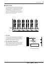
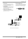
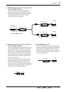
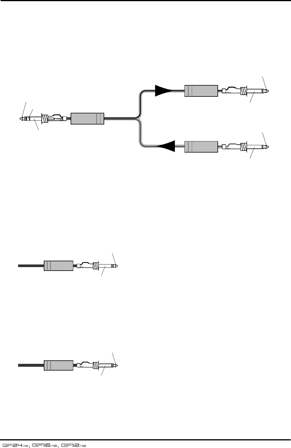
B ST INSERT I/O jacks
These are TRS phone input/output jacks for
inserting external effect processors between the
ST bus and the STEREO fader. The nominal
input/output level is 0 dB. The pin wiring is
shown in the following diagram.
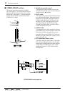
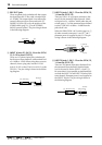
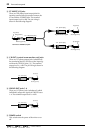
C C-R OUT (control room monitor out) jacks
These are 1/4" phone output jacks (unbalanced)
for monitoring the PFL/AFL bus or the input sig-
nal from the TAPE IN jacks (4). The nominal
output level is +4 dB. The pin wiring is shown in
the following diagram.
D GROUP OUT jacks 1–4
These are 1/4" phone jacks (unbalanced) which
individually output the signals of GROUP buses
1–4. The nominal output level is +4 dB.
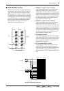
E POWER switch
This switch turns the power of the mixer on or
off.
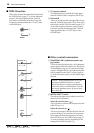
1/4" phone plug
1/4" phone plug
1/4" TRS phone plug
To processor’s input
From processor’s output
Connect to INSERT I/O jack
Tip (send)
Tip (send)
Ring (return)
Sleeve (ground)
Sleeve (ground)
Tip (return)
Sleeve (ground)
1/4" phone plug
Tip (send)
Sleeve (ground)
1/4" phone plug
Tip (send)
Sleeve (ground)