


18 Front and rear panel
—Owner’s Manual
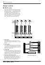
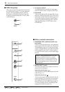
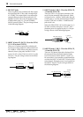
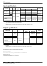
5 REC OUT jacks
These are phono jacks (unbalanced) that output
the signal from the ST bus, with a nominal level
of –10 dBV. This output signal is not affected by
external effect processors connected to the ST
INSERT I/O jacks (B) or by the position of the
STEREO fader (page 12, 3 in the STEREO/
MONO control section). The pin wiring is shown
in the following diagram.
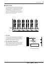
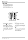
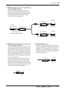
6 INPUT A jacks 21–24 {13–16 on the GF16/
12, 9–12 on the GF12/12}
These are 1/4" phone input jacks (unbalanced)
for the stereo input channels, with nominal level
of +10 dB to –34 dB. When using these as mono
channels, insert a plug only into the 21L/23L
jacks {13L/15L on the GF16/12, or 9L/11L on the
GF12/12}. The pin wiring is shown in the follow-
ing diagram.
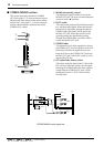
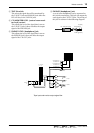
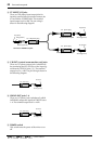
7 INPUT A jacks 1–20 {1–12 on the GF16/12,
1–8 on the GF12/12}
These are XLR-3-31 type input connectors (bal-
anced) for the monaural input channels. Nomi-
nal input level is –16 dB to –60 dB when the pad
switch (page 6, 1 of the monaural input channel
section) is off, and +10 dB to –34 dB when the
pad switch is on.
When the PHANTOM +48 V switch (page 14, 1
of other controls/connectors) is on, DC +48 V
phantom power is supplied to pins 2/3. The pin
wiring is shown in the following diagram.
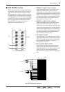
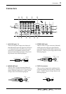
8 INPUT B jacks 1–20 {1–12 on the GF16/12,
1–8 on the GF12/12}
These are TRS phone input jacks (balanced) for
the monaural input channels. Nominal input
level is the same as for the INPUT A jacks (7).
Be aware that it is not possible to simultaneously
use both the INPUT A and INPUT B jacks of the
same channel. Phantom power is not supplied to
the INPUT B jacks. The pin wiring is shown in
the following diagram.
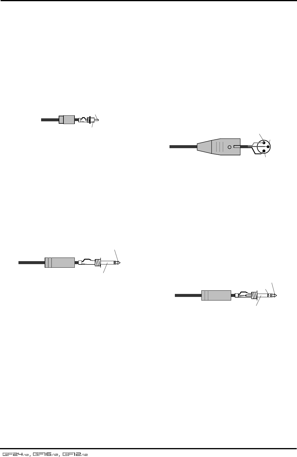
Phono plug
Tip
Sleeve
1/4" phone plug
Tip (send)
Sleeve (ground)
Male XLR connector
1 (ground)
3 (cold)
2 (hot)
1/4" TRS phone plug
Tip (hot)
Ring (cold)
Sleeve (ground)