


The Controls and Connectors
Front Panel
DME64N/DME24N Owner’s Manual
14
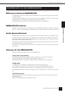
Front Panel
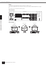
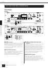
1 [USB] Connector
A computer can be connected here when it is necessary to
program or control the device. When a USB connection is
to be used, the USB-MIDI driver must be installed on the
computer. Refer to the DME Designer Installation Guide
for installation instructions.
2 [EXT. CLOCK] Indicator
When a clock signal from an external device is selected, the
indicator will light green. If the clock signal is not
appropriate the indicator will flash red. The indicator will
go out when the internal word clock is selected.
3 [96kHz] [88.2kHz] [48kHz] [44.1kHz]
Indicator
Normally, the indicator corresponding to the current word
clock frequency will light green. If a problem with the
master clock is detected all of these indicators will flash red.
2 seconds after a problem is detected with an external
master clock the internal clock will temporarily be selected.
When this happens the indicator corresponding to the
frequency of the internal clock will light green, and all
other indicators will continue to flash red.
4 [NETWORK] Indicator
Lights while data communication is occurring via the
[USB], [NETWORK], or [CASCADE] connector.
Received data causes the indicator to light in green, while
transmitted data causes the indicator to light in orange. If a
problem occurs the indicator will light in red.
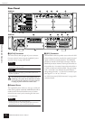
The Controls and Connectors
HOMEHOME UTILITYUTILITYSCENESCENE LEVELLEVEL MUTEMUTE
ENTERENTERCANCELCANCEL
HOMEHOME UTILITYUTILITYSCENE LEVELLEVEL MUTEMUTE
ENTERENTERCANCELCANCEL
1
1
2
4
5
6
7
8
7
8
9
9
)
)
^
&
^
&
º
¡
™
£
º
¡
™
£
*(
*(
! @#$%
! @#$%
2
4
5
6
3
3
DME64N
DME24N