


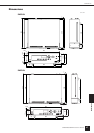

References
Input/Output Characteristics
DME64N/DME24N Owner’s Manual
63
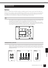
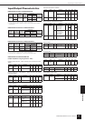
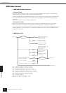
Input/Output Characteristics
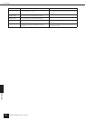
DME24N ANALOG INPUT CHARACTERISTICS
• 0dBu = 0.775 Vrms
• All AD converters (CH1-8) are 24-bit linear, 128 times oversampling.
• +48V DC (phantom power) is supplied to CH INPUT (1-8) connectors via each individual
controlled switch.
DME64N ANALOG OUTPUT CHARACTERISTICS
• 0dBu = 0.775 Vrms
• Stereo Phone Jack = unbalanced (Tip = LEFT, Ring = RIGHT, Sleeve = GND)
DME24N ANALOG OUTPUT CHARACTERISTICS
• 0dBu = 0.775 Vrms
• All AD converters (CH1-8) are 24-bit linear, 128 times oversampling.
• Stereo Phone Jack = unbalanced (Tip = LEFT, Ring = RIGHT, Sleeve = GND)
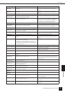
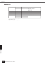
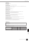
DME24N ANALOG CHARACTERISTICS
(Output impedance of signal generator: 150Ω)
Frequency Response 20Hz – 20kHz, reference to the nominal output level
@1kHz
Frequency Response fs = 96kHz@20Hz – 40kHz, reference to the nominal
output level @1kHz
Gain Error @1kHz
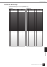
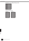
Total Harmonic Distortion fs = 48kHz
Total Harmonic Distortion fs=96kHz
Hum & Noise EIN = Equivalent Input Noise
• Hum & Noise are measured with a 6dB/octave filter @12.7kHz; equivalent to a 20kHz filter
with infinite dB/octave attenuation.
Dynamic Range
• Dynamic range are measured with a 6dB/octave filter @12.7kHz; equivalent to a 20kHz filter
with infinite dB/octave attenuation.
Crosstalk@1kHz
Maximum Voltage Gain@1kHz
Phantom Voltage
PEAK/SIGNAL Indicator Level
Terminals Gain
Actual
Load
Impedance
For Use
With
Nominal
Input Level
Connector
Nominal
Max.
before clip
CH INPUT
1 – 8
-60dB 3kΩ 50 – 600Ω
Mics &
600Ω
Lines
-60dBu
(0.775mV)
-40dBu
(7.75mV)
Euroblock
+10dB +10dBu
(2.451V)
+30dBu
(24.511V)
Output
Terminals
Actual
Source
Impedance
For Use With
Nominal
Output Level
Connector
Nominal
Max. before
clip
PHONES 15Ω 8Ω 75mW 150mW Stereo
Phone Jack
40Ω 65mW 150mW
Output
Terminals
Actual
Source
Impedance
For Use With
Nominal
Output Level
Connector
Nominal
Max. before
clip
OUTPUT
1 – 8
150Ω 600Ω Lines +4dBu
(1.23V)
+24dBu
(12.28)
Euroblock
PHONES 15Ω 8Ω 75mW 150mW Stereo
Phone Jack
40Ω 65mW 150mW
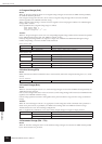
Input Output RL Conditions Min. Typ. Max. Units
CH INPUT
1 – 8
CH
OUTPUT
1 – 8
600Ω GAIN = -60dB -1.5 0.0 0.5 dB
Internal
OSC
PHONES 8Ω -3.0 0.0 0.5 dB
Input Output RL Conditions Min. Typ. Max. Units
CH INPUT
1 – 8
CH
OUTPUT
1 – 8
600Ω GAIN = -60dB -1.5 0.0 0.5 dB
Internal
OSC
PHONES 8Ω -3.0 0.0 0.5 dB
Input Output RL Conditions Min. Typ. Max. Units
CH INPUT
1 – 8
CH
OUTPUT
1 – 8
600Ω GAIN = -60dB 2.0 4.0 6.0 dBu
GAIN = +10dB 2.0 4.0 6.0 dBu
Internal
OSC
PHONES 8Ω -30dBFS @1kHz,
phones level control:
max.
-2.0 0.0 2.0 dBu
Input Output RL Conditions Min. Typ. Max. Units
CH INPUT
1 – 8
CH
OUTPUT
1 – 8
600Ω GAIN = -60dB
@20Hz – 20kHz
@+14dBu
0.1 %
GAIN = +10dB
@20Hz – 20kHz
@+14dBu
0.05 %
Internal
OSC
PHONES 8Ω -30dBFS @1kHz,
phones level control:
max.
0.1 %
Input Output RL Conditions Min. Typ. Max. Units
CH INPUT
1 – 8
CH
OUTPUT
1 – 8
600Ω GAIN = -60dB
@20Hz – 20kHz
@+14dBu
0.1 %
GAIN = +10dB
@20Hz – 20kHz
@+14dBu
0.05 %
Internal
OSC
PHONES 8Ω -30dBFS @1kHz,
phones level control:
max.
0.1 %
Input Output RL Conditions Min. Typ. Max. Units
CH INPUT
1 – 8
CH
OUTPUT
1 – 8
600Ω GAIN = -60dB
Master fader at
nominal level and
one Ch fader at
nominal level.
(Mixer mode)
-128
EIN
dBu
-64 dBu
600Ω GAIN = +10dB
Master fader at
nominal level and
one Ch fader at
nominal level.
(Mixer mode)
-82 dBu
Internal
OSC
PHONES 8Ω Residual output
noise, phones level
control: min.
-86 dBu
Input Output RL Conditions Min. Typ. Max. Units
CH INPUT
1 – 8
CH
OUTPUT
1 – 8
600Ω GAIN = +10dB 106 dB
From/To To/From Conditions Min. Typ. Max. Units
CH N CH (N-1) or
(N+1)
CH1 – 8, adjacent
inputs
-80 dB
Input Output RL Conditions Min. Typ. Max. Units
CH INPUT
1 – 8
CH
OUTPUT
1 – 8
600Ω GAIN = -60dB 64 dB
Output Conditions Min. Typ. Max. Units
CH INPUT
1 – 8
hot, cold: No load 46 48 50 V
Input Output Conditions Min. Typ. Max. Units
CH INPUT
1 – 8
CH
OUTPUT
1 – 8
GAIN = +10dB PEAK
red LED: ON
19 21 23 dBu
GAIN = +10dB SIGNAL
green LED: ON
-18 -16 -14 dBu