


Connecting to an External Device
GPI Connection ([GPI] Connectors)
DME64N/DME24N Owner’s Manual
33
GPI Connection ([GPI] Connectors)
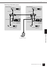
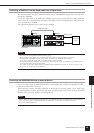
GPI (General Purpose Interface) device (GPI controller, etc.) can be connected to the rear-panel [GPI]
connectors. Using GPI a variety of control signals can be transferred between the DME64N/24N and external
controllers or other devices. The optional CP4SW, CP4SF, and CP1SF control panels are also connected via
GPI.
The DME64N provides 16 channels of GPI input and output, and the DME24N provides 8 channels. Each
channel has an IN terminal, a +V terminal, an OUT terminal and a GND terminal. The +V terminals have an
open-terminal voltage of 5 volts. The IN terminals can detect a full range of input voltages from 0V through
5V, while the OUT terminals output either signal “L” or “H” at a TTL level.
The parameters for each GPI input and output are assigned via the DME Designer application.
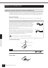
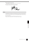
Euroblock connectors are used for all GPI input and output connections. Euroblock connection methods are
described in “Euroblock Connection” on page 26 in this manual.
NOTE
For more information on the CP4SW, CP4SF, and CP1SF control panels refer to “CP4SW, CP4SF, and CP1SF” in the
Appendix of this manual (page 53).
NOTE
The DME Designer can be used to set up the system so that scene recall operations and user parameter control can be carried
out from connected GPI control devices. Refer to the DME Designer manual for details.
NOTE
GPI connector calibration procedure is described on page 53 of this manual, in the Utility display GPI page.
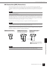
IN +V
IN +V GND
OUT GND
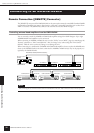
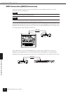
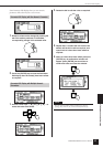
Example: Controlling the
DME64N/24N from a switch.
GPI Connection
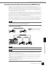
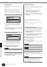
Example: Controlling the
DME64N/24N via a 10k ohm
linear taper potentiometer.
GPI Connection
Continuous
potentiometer
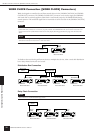
GPI Connection
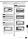
Example: Lighting external
LED indicators from the
DME64N/24N.
Max. 16mA
Make sure that the current between
the OUT and GND [GPI] connectors
is less than 16mA.
CAUTION