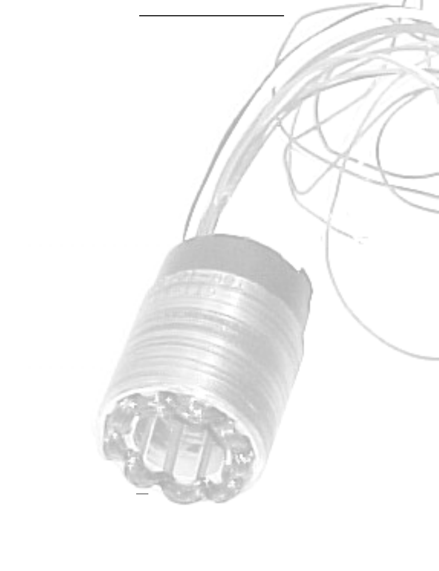
BRUSHLESS DC MOTOR
Maximum Continuous Stall Torque (T
C
) is the amount of torque produce at zero speed, which results
in a 100 Cº rise in temperature. Generally the highest operation temperature that should be allowed is
150 Cº and is a combination of the ambient temperature and the temperature rise for a given operating
condition.
Maximum rated Torque (T
R
) is the amount of torque that the motor can produce without demagnetizing
the rotor. The torque is only available for short durations. Also, it may not be possible to produce the
Maximum rater torque because of limitations of voltage and current (see peak torque).
Motor Constant (K
M
) is the rations of the peak torque to the square root of the input power at stall
which 25 Cº ambient temperature. The ratio is useful during the initial selection of a motor since it
indicated the ability of the motor to convert electrical power into torque.
K
M
= T
P
(Peak Torque / √P
P
(Peal Input Power)
Or
K
M
= K
T
(Torque Constant / √R
M
(Terminal Resistance)
Electrical Time Constant ( t
F
) is the ration of inductance (L
M
) IN henries, to the resistance R
M
IN
ohms. This is the inductance and resistance as measured across any two phases in a delta or wye
configuration.
T
E
= L
M
/ R
M
Mechanical Time Constant (t
M
) is the time required to reach 62.3% of the motor maximum speed after
the application of constant DC voltage trough the commutation, ignoring friction, wind age and cross
losses.
T
M
= J
M
* R
M
/ K
T
*K
B
Thermal Resistance (TPR) correlated winding temperature rise to the average power dissipated in the
stator winding. The published TPR assumes that a housed motor is mounted to an aluminum heat sink
of specific damnations. Additional cooling from forced air, water jacketing, or increased heat sinking
decreases the motor Thermal Resistance allowing higher power output then the published date.
Viscous damping (F
0
) gives an indication of the torque lost due to B.E.M.F in the motor when the
source impedance is zero. F
0
value can be represented as F
0
= K
T.
Maximum Cogging Torque (T
F
) is principally the static friction torque felt as the motor is rotated as low
speed. The published value does not include the bearing friction of a housed motor.
Number of Poles ( N
P
) is the number of permanent magnet poles of the rotor. For the QB Series this is
generally a total of six (three north and three south)
Design Voltage (V
P
) is the nominal voltage required to produce the peak torque when the rotor speed is
zero and the winding temperature is 25 ºC. as such V
P
is the product of I
P
and R
M
. at any temperature
greater then 25 ºC, the required voltage to produce peak torque increases due to the increase in winding
resistance. The design voltage is not
a limit but a reference point for the date.
Peak Torque (t
P
) is the nominal value of developed torque with the rated current I
P
applied to the
windings. For each winding specified the product of peak current (I
P
) and nominal torque sensitivity (k
T
)
gives T
P
unless the maximum rated torque (T
R
) is reached.
Peak Current (I
P
) is the rated current used to obtain the nominal peak torque from the motor with
nominal torque sensitivity (K
T
). I
P
is generally the design voltage divided by the terminal resistance (R
M
).
Torque Sensitivity (k
T
) is the ratio of the developed torque to the applied current for a specific winding.
K
T
is related to the BEMF constant K
B
.
No load Speed (S
LN
) is the theoretical no load speed of the motor with the design voltage applied.
BEMF Constant (k
B
) is the ration of voltage generated in the winding to the speed of the rotor. K
B
is
proportional to K
T
.
Terminal Resistance (R
M
) is the winding resistance measured between any two leads of the winding in
either a delta or wye configuration at 25 ºC.
Terminal Inductance (L
M
) is the winding inductance measured between any two leads of the winding in
either a delta or wye configuration at 25ºC.
12


