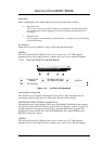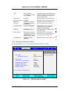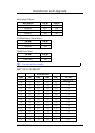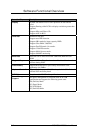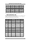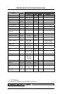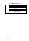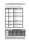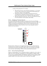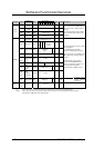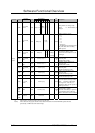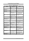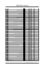
Pin Assignments
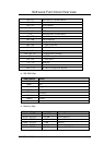
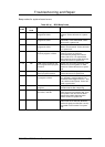
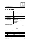
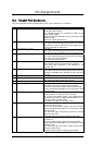
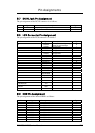
14 AFD#/DSB#_D14,_P14/_D12:O,O/O This output goes low to cause the printer to automatically
feed one line after each line is printed.
The AFD# output is the complement of bit 1 of the printer
control register.
Refer to parallel pot description for use of this pin in ECP
and EPP mode.
15 ERR#/HDSEL_T/D12:I/O A low on this input from the printer indicates that there is
a error condition at the printer.
Bit 3 of the printer status register reads the ERR# input.
Refer to parallel port description for use of this pin in ECP
and EPP mode.
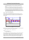
This high current output selects the floppy disk side for
reading or writing.
A logic “1” on this pin means side 0 will be accessed
while a logic “0” means side 1 will be acessed.
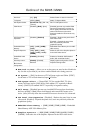
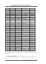
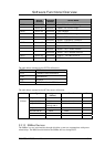
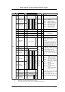
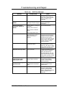
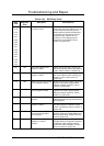
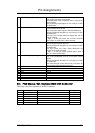
16 INIT#/DIR#_D14,_P14/D12:O,O/O This output is bit 2 of the printer control register. This is
used to initiate the printer when low.
Refer to parallel port description for use of this pin in ECP
and EPP mode.
This high current low active output determines the
direction of the head movement.
A logic “1” on this pin means outward motion, while a
logic “0” means inward motion.
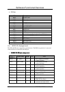
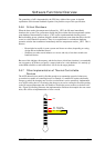
17 SLIN#/STEP#_D14,_P14/_D12:O,O/O This active low output selects the printer.
This is the complement of bit 3 of the printer control
register.
Refer to parallel port description for use of this pin in ECP
and EPP mode.
This active low high current driver issues s low pulse for
each track to track movement of the head.
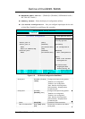
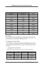
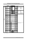
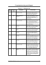
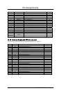
18 GND: Ground
19 GND: Ground
20 GND: Ground
21 GND: Ground
22 GND: Ground
23 GND: Ground
24 GND: Ground
25 GND: Ground
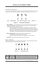
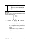
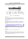
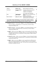
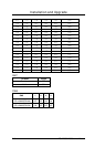
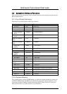
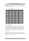
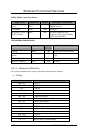
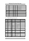
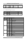
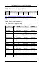
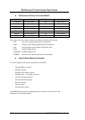
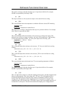
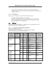
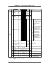
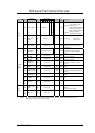
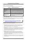
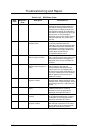
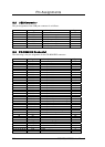
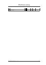
B.4 PS/2 Mouse / Ext. Keyboard Mini-DIN Connector
Following is the pin assignment of the PS/2 connector:
No Signal Description Type
1 MOUSE_CLK External clock for mouse or keyboard I/O
2 EKB_CLK External clock for mouse or keyboard I/O
3 +5vs 5v power supply O
4 Gnd Ground I
5 EKB_DATA External data for mouse or keyboard I/O
6 MOUSE_DATA External data for mouse or keyboard I/O
FIC M295 / M296 Service Manual B-3