


Serial Output Specification
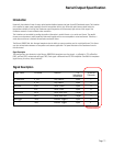
The interface to the M3000SiDAA Interpolator uses the following signals to implement serial communication, n_spiEnable
(n_CS), spiDataOut (SDO), spiClockIn (SCK), and optionally spiClockOut (SCF). Each signal is differential and RS-422 compatible.
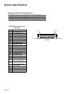
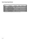
See table for interpolator signal names, pin names, and pin locations
I/O 15 Pin HD
Interpolator Connector
Signal Name Pin Name Function Referenced Pin Number
n_spiEnable n_CS+ Chip Select+ Input 7
n_CS- Chip Select- Input 8
spiClockIn SCK+ Serial Clock+ Input 14
SCK- Serial Clock- Input 15
spiDataOut SDO+ Serial Data Output+ Output 5
SDO- Serial Data Output- Output 4
spiClockOut SCF+ Serial Clock Feedback+ Output 10
SCF- Serial Clock Feedback- Output 9
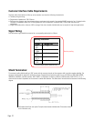
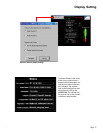
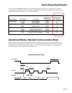
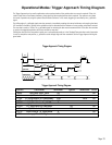
Operational Modes: Standard Communication Mode
The falling edge of the n_spiEnable signal loads the current data word into the output buffer. The serial data (MSB) is valid
80ns (typical) after the falling edge of n_spiEnable signal. The n_spiEnable signal is kept asserted while spiClock signal shifts
out the rest of the data bits. Each serial data bit is valid on the falling edge of the spiClock signal. The n_spiEnable should
return to High after the last serial data bit has been shifted out
tV
tCSD
tspiH
tspiL
tCCS
tCS
n_spiEnable
spiClocK
spiDataOut
tCSC
MSB
LSB
Clk1
Clk36
Communication Mode Timing
Page 21
Revision pending.