


Installation Instructions
Linear Encoders - Mounting
Page 4
1
2
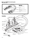
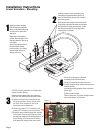
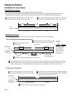
Install the sensors on your mounting surfaces
referencing the appropriate datum surface as
shown on the interface drawing. Use 2 washers
per mounting screw.
Benching pins may be used to locate each sensor
if the system mechanical tolerances are adequate.
See data sheet for alignment tolerances, or keep
mounting screws loose for sensor alignment if
benching pins are not used.
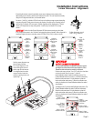
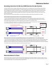
Attach the scale to the base
slide. Reference the preferred
datum on the interface drawing
for either end or center index
orientation.
Depending on the mounting
method, attach the scale to the
slide with adhesive. Refer to pg.
8 for details.
Be sure the grating surface of
the scale faces the sensor.
Insure that there is no contact
between these surfaces or
damage may result.
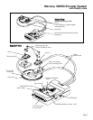
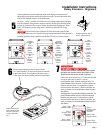
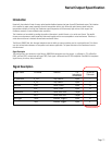
Be sure the source power is off before
connecting the SmartPrecision plug.
Connect the SmartPrecision electronics to the
controller using the pinout diagram described on the
interface drawing.
Insure proper system grounding. Refer to the proce-
dure on pg 9.
Tighten the thumb screws.
Power up the system. The Power and Signal indica-
tors for both sensors will illuminate.
4
3
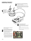
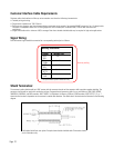
CAUTION: observe precautions for handling elec-
trostatic sensitive devices.
Route the sensor cables through your equipment
to the Dual Axis SmartPrecision electronics module.
A) Remove the three cover screws and the top
half of the connector housing. Do not pull on
the 25-pin D-sub connector or the circuit
board under the insulation layer.
B) Attach each sensor's 5 X 2 connector to the
mating 5 X 2 connector on the circuit board.
C) Route the sensor cables through their channels
in the center of the connector body and place
the cable's hex sleeves in the matching recesses.
Attach the top half of the connector housing
to the bottom half using the three cover screws.
Sensor 2
Sensor 1