


10 ULTRADRIVE PRO DCX2496 User Manual
When this function is On, the display provides a warning note that shows both
the new link to be activated and the name of the inputs that will be overwritten
(black eld). Use the data wheel to edit the link to be activated (black eld).
Thevalues of input A will be transferred to the following inputs.
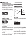
Possible setting
Newlink OFF A + B A + B + C A + B + C + SUM
Overwritten settings (empty) B B+C B+C+SUM
Tab. 4.2: In Stereo Link
When you edit a setting of any input, while a link is activated, all edits are
directly transferred to the linked inputs. In the case of the IN STEREO LINK
function, this also includes the DELAY values (see chapter 4.3.2).
Use the parameter IN A + B SOURCE to select the type of input signals:
ANALOGor AES/EBU (digital: via input A only).
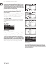
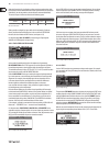
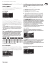
4.2.2 DLY-CORR./AUTO-ALIGN
Fig. 4.11: Setup ➠ Dly-Corr./Auto-Align
As the speed of sound depends on the air temperature, the parameter
DELAY CORRECTION on this SETUP page can be used to adjust the DCX2496 to
the ambient temperature, ensuring proper delay characteristics at all times.
Theavailable value range is from -20°C to 50°C (-4°F to 122°F) and will be taken
into account only as long as DELAY CORRECTION is ON.
With the AUTO ALIGN function you can delay the output signal automatically
by a certain amount, so as to eliminate phase cancellations caused by speaker
alignment. For example, when the diaphragms of several speakers are not
in the same phase it leads to cancellations due to arrival time dierences.
Identicalsignals are radiated from dierent positions, so that wave
crests coincide with wave troughs. If only one of these signals is delayed,
thismisalignment can becompensated.
If the arival time dierences are smaller, a short signal delay will be enough
to eliminate them (SHORT DELAY). However, if the speaker cabinets are placed
several meters away from each other, not only can phase cancellations occur
but so can audible run-time dierences. To remove these, you’ll have to use
considerably higher delay values (LONG DELAY). The LONG DELAY calculation,
however, works only with a minimum distance of four meters.
If, for example, a speaker is connected with incorrect polarity, AUTO ALIGN will
detect and—if POLARITIES is on—correct this error automatically.
Use the parameters SHORT DELAY, LONG DELAY and POLARITIES for the
automatic correction of output signals. As soon as at least one parameter is set to
YES, pressing OK will take you to another sub-menu. If not (all parameters set to
NO), you will be warned that the process cannot be executed.
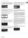
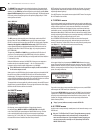
Fig. 4.12: Setup ➠ Dly-Corr./Auto-Align
In the AUTO-ALIGN sub-menu you can mute or open all outputs. Be sure that at
least two outputs are open (UNMUTE OUTPUTS TO ALIGN), otherwise no delay
values can be calculated, and a warning message will be displayed.
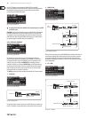
Fig. 4.13: Setup ➠ Dly-Corr./Auto-Align
If at least two or more outputs have been opened and OK has been pressed,
the cursor will jump to ADJUST NOISE LEVEL and you can hear some test noise.
Usethe data wheel to adjust the test noise. The level will be read at the outputs.
Press OK to trigger the measuring process. The DCX2496 calculates the run-time
dierences, phase shift and polarity. The OUTs are automatically adjusted to the
optimum delay values calculated. This process cannot be executed if the test
noise level is too low.
Fig. 4.14: Setup ➠ Dly-Corr./Auto-Align
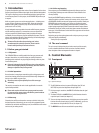
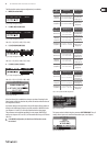
4.2.3 COPY
Use the COPY function to copy parameter settings to other pages. For example,
you can transfer the EQ or gain settings from one channel to another, which saves
you a lot of time.
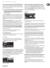
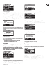
Fig. 4.15: Setup ➠ Copy
The parameter COPY MODE determines whether only single pages (PAGE) or the
complete channel settings (WHOLE CHANNEL) will be copied. Select PAGE mode
with the PARAM button and then select the source channel SOURCE plus the
SOURCE PAGE to be transferred to another channel. If you select just one page,
the channel to be overwritten (DESTINATION PAGE) will appear automatically
under the parameter DESTINATION. Please enter the channel to which the data
should be copied to (DESTINATION CHANNEL).
Both the source and destination Channel can be selected using the data wheel or
by pressing the corresponding channel button (IN A-C, OUT 1-6 and SUM).
Fig. 4.16: Setup ➠ Copy