


12 ULTRADRIVE PRO DCX2496 User Manual
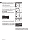
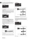
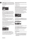
On this SETUP page you can activate the GLOBAL LOCK function (ON),
entera password, then conrm with OK. Now, if you try to edit any parameter,
thedisplay will prompt you to enter your password. The process follows
the same logic as the PAGE LOCK routine.
Fig. 4.23: Setup ➠ Global Lock
◊ Activating PAGE LOCK and/or GLOBAL LOCK auto matically locks all STORE
and RECALL pages.
CAUTION: If you have locked individual pages with PAGE LOCK and deactivated
the GLOBAL LOCK function with the correct password, you can not yet make
any changes to the corresponding page. You must rst unlock this page in the
PAGE LOCK menu. When using the GLOBAL LOCK feature, we recommend that
you unlock all pages in the PAGE LOCK menu (UNLOCK ALL).
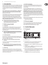
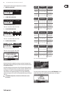
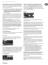
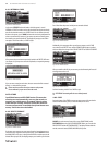
4.2.6 MISCELLANEOUS
Fig. 4.24: Setup ➠ Miscellaneous
On this page, the current version of your DCX2496 operating software is
shown in the top right corner of the display (e.g. VERSION: 1.0). This is just a
message and cannot be selected. Additionally, this menu provides ve user
settings. Firstly,you can adapt the CONTRAST of the display to ambient
conditions. Secondly,you can assign a DEVICE ID to your DCX2496, allowing
you to daisy-chain several units via the rear panel RS-485 network interface
(LINK A and B). The rst unit is connected to a PC either via one of the LINK
interfaces (RS-485) orvia the RS-232 interface.
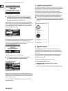
The PORT parameter provides three dierent modes for the PC remote control:
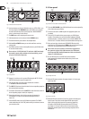
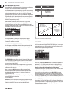
1. PC (RS-232)
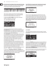
Fig. 4.25: Setup ➠ Miscellaneous
PC (RS-232) =
RS-232
DCX2496
DEVICE ID: 1
PORT: PC (RS-232)
PC
Fig. 4.26: PC (RS-232) mode
Use this setting if you want to connect only one DCX2496 to your computer via
the RS-232 interface. It is impossible to daisy-chain several units in this mode.
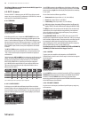
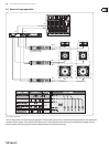
2. LINK (RS-485)
Fig. 4.27: Setup ➠ Miscellaneous
LINK
(RS-485) =
PC
RS-485
RS-485
RS-485
DEVICE ID: 1
PORT: LINK (RS-485)
DCX2496
DCX2496
DCX2496
DEVICE ID: 2
PORT: LINK (RS-485)
DEVICE ID: 3
PORT: LINK (RS-485)
TERM-Switch: ON
Fig. 4.28: LINK (RS-485) mode
Please use this mode when several ULTRADRIVE PROs are linked to each other via
the network interfaces LINK A and B and the rst unit in the chain is connected
to a computer via the RS-485 interface. The last unit in the chain must have a
termination (TERM switch on rear panel = ON). The RS-232 interface is not used
in this conguration.
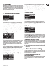
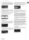
3. PC -> LINK
Fig. 4.29: Setup ➠ Miscellaneous
PC -> LINK =
PC
RS-232
RS-232
RS-232
DEVICE ID: 1
PORT: PC -> LINK
DEVICE ID: 2
PORT: LINK (RS-485)
DEVICE ID: 3
PORT: LINK (RS-485)
TERM-Switch: ON
TERM-Switch: ON
DCX2496
DCX2496
DCX2496
Fig. 4.30: PC -> LINK mode