


7 ULTRADRIVE PRO DCX2496 User Manual
3. Quick Start
This chapter is for those who cannot wait to use their new DCX2496 in a practical
application. You will nd a description of how you can explore your DCX2496 and
its versatile and intuitive features below. This chapter is just a starting point for
future excursions. So, please read the entire user’s manual to take full advantage
of all your DCX2496’s features and functions.
Please work your way through the following six chapters (3.1 to 3.6), one after
the other. Here we go!
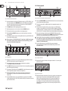
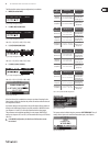
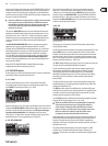
3.1 Selecting an output conguration
Fig. 3.1: Setup ➠ In/Out
Press the SETUP button to call up the SETUP menu. On the rst menu page,
selectan output conguration
(OUT CONFI GURATION) to determine which
outputs are used for which frequency ranges. One mono and three stereo
congurations areavailable.
The mono conguration allows you to split the input signal into six dierent
frequency ranges. The stereo congurations allow a maximum of three dierent
frequency ranges per stereo side. The abbreviations L, M and H stand for Low,
Mid and High Speaker. For more information see chapter 4.2.1 “IN/OUT”.
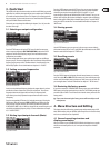
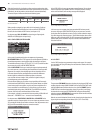
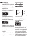
3.2 Setting crossover frequencies
Fig. 3.2: Out ➠ X-Over Points
In order to assign dedicated frequency bands to the output channels, you have
to dene the crossover frequencies (X-Over) for each of them. The crossover
frequencies determine the upper and lower limits of a frequency band,
whichallows you to clearly separate the outputs from each other in terms
offrequency.
Press the corresponding OUT button (1-6) and select menu page 2/8 using the
PAGE buttons. With the parameters FREQ and TYPE you can dene the slope
of the crossover frequency and also select a lter type. When the parameter
X-OVER ADJUST MODE is set to “LINK”, any changes to the crossover frequency will
also shift the neighboring frequency ranges. For more information see chapter
4.5.2“XOVER POINTS”.
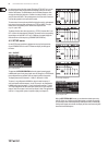
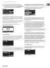
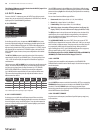
3.3 Muting input/output channels (Mute)
Fig. 3.3: Mute ➠ Select
Press the MUTE button to enter the MUTE menu. Here you can mute the inputs
and outputs of the DCX2496. On this page you can mute or activate individual
channels by pressing the channel buttons (IN A/B/C and OUT 1-6), or all
inputs/outputs by pressing the PARAM and OK or CANCEL buttons. Thus, you can
monitor each frequency band, either individually or together with a neighboring
band, to allow perfect editing of the isolated frequency range. To quit the MUTE
menu press MUTE a second time. For more detailed information see chapter 4.6
“MUTEmenu”.
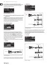
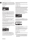
3.4 Storing presets
Fig.: 3.4: Store ➠ Internal/Card
Use the STORE button to save your presets. In this menu you can store either in
the internal memory (INT) or on a PC card (CARD). More information on the STORE
function can be found in chapter 4.8 “STORE menu”.
3.5 Recalling presets
Fig. 3.5: Recall ➠ Internal/Card
Press the RECALL button to load presets from the internal memory or a memory
card. Select either INT or CARD (PCMCIA memory card), then enter the preset you
wish to recall. We included some typical presets, which you can use as a basis for
your own applications. For further information see chapter 4.7 “RECALL menu”.
3.6 Restoring the factory presets
If you wish to restore the ULTRADRIVE PRO’s factory presets, press and hold both
PAGE buttons on the front panel switching on the unit. The DCX2496 prompts you
to conrm (OK) or CANCEL. Press OK to erase the internal memory and restore the
factory presets.
◊ Please note that restoring the factory presets will irrevocably erase all
edited presets.
4. Menu Structure and Editing
This chapter describes all functions, operating steps and parameter pages in full
detail. While working with your DCX2496, please keep the user’s manual on hand,
and use it as a reference in case of problems.
4.1 General operating structure and
displaypresentation
When you switch on your ULTRADRIVE PRO DCX2496, the display shows a graphic
with the current routing of the unit, i.e. how inputs and outputs are linked to
each other.