


13 ULTRADRIVE PRO DCX2496 User Manual
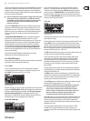
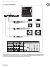
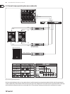
Please use this mode on the rst unit when several ULTRADRIVE PROs are linked
to each other via LINK A and B, and the rst unit in the chain is connected to a
computer via the RS-232 interface. In this conguration, the last AND the rst
unit in the chain must have their TERM switch ON, since both are integrated into
the system via only one LINK interface.
◊ General rule: Whenever one device within a chain has been connected
to the system via only one LINK interface, its TERM switch must be
pressed (ON) to avoid data reflections and hence transmission errors.
In PC (RS-232) mode this switch is not needed because the LINK
interfaces are not used.
The parameter DELAY UNIT determines the units of both measurement and
temperature used for the delay settings in the corresponding menus. You can
choose between m / mm / C° and ft / in / F°. When you change from meters/
millimeters to feet/inch, the temperature will be changed automatically from
°Celsius to °Fahrenheit. These settings cannot be made independently of
eachother.
The MUTE OUTS WHEN POWER ON function is used to protect connected
equipment such as power amps and loudspeakers. When it is on (YES),
alloutputs of the ULTRADRIVE PRO are muted during power-up. To restore the
output conguration of your presets, you will have to activate the respective
outputs individually or call up the preset again using RECALL (see chapter
4.7). UsingRECALL to switch from one preset to another automatically mutes
all outputs, as soon as a preset has a dierent output conguration.
However, if the output congurations are the same, the muted outputs of the
new preset will beloaded.
When MUTE OUTS WHEN POWER ON is disabled (NO), the last output
conguration used will be recalled during power-up.
4.3 IN A/B/C menu
On these pages you can dene the EQ, delay and similar values for the individual
input signals, and hence optimize the overall sound.
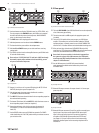
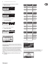
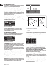
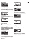
4.3.1 GAIN
Press one of the buttons IN A, IN B or IN C to enter the INPUT menu of the
corresponding input. On the rst page, you can adjust the input gain for the
signal (GAIN). The setting range is from -15 to +15 dB.
Fig. 4.31: In A ➠ Gain
Below this parameter you can see a graphic representation of the current IN-OUT
conguration (OUTPUT CONFIG). Additionally, the display shows whether or not
the input is used for the SUM signal (see chapter 4.4). This is just a message.
Youcannot edit anything here! OUT congurations are shown on the
SETUP page 1/6. The input source selection for SUM and for the various OUTs is
determined on page 1 in the corresponding menus (SUM, OUT).
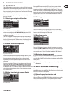
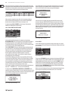
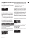
4.3.2 DELAY/NAME
Fig. 4.32: In A ➠ Delay/Name
You can delay either the IN A, B or C signal to compensate for arrival time
dierences—resulting from oset stereo signals or so-called “delay lines”
(“delay towers”). Activate the function with DELAY (ON) and select the delay
time of your choice with DISTANCE/TIME. The values DISTANCE and TIME are
linked to each other, i.e. both values are edited simultaneously when you turn
the data wheel. IN A (B/C) NAME allows you to enter a name with a maximum of
8characters for the input signal selected.
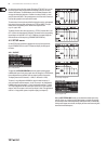
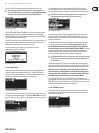
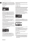
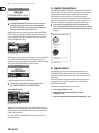
4.3.3 EQ
Fig.4 .33: In A ➠ EQ
On this page you can process the sound of the input signals with the help of
various equalizer settings.
The EQ parameter determines whether this function is generally ON or OFF. Inthe
adjacent NR eld you can select the number of EQs. There are various lters
available, which can be used and edited. Their number depends on the current
processor capacity, which is shown as a percentage next to the number of the
lter. The free capacity of the processor is directly dependent upon the number
and type of the lter selected (e.g. >FREE: 33%).
Use TYPE to dene the lter type you wish to use. You can choose from low-pass
(LP), high-pass (HP) and band-pass (BP) lters. Description:
The low-pass lter raises (positive gain) or lowers (negative gain) the level
of the frequency band below the adjusted frequency. The high-pass lter
raises (positive gain) or lowers (negative gain) the level of the frequency
band above the adjusted frequency. Use TYPE to set a slope of 6 or 12 dB/oct.
for the high-pass or low-pass lter, or to determine the quality (Q) of the
band-pass lter.
The band-pass lter raises or lowers the level of the frequency range around
the adjusted frequency. The quality parameter Q determines the width of the
resulting bell-shaped lter curve.
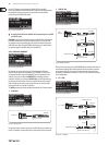
The FREQ parameter controls the cuto frequency, at which the lter starts
working. In the case of the low-pass and high-pass lters, the cuto frequency
is the point, at which low and/or high frequencies are processed. The entire
frequency spectrum ranges from 20 Hz to 20 kHz.
Use the GAIN parameter to dene the degree of boost/cut applied to a specic
frequency band. The setting range is from -15 to +15 dB.
◊ When you set GAIN to 0 dB, the corresponding filter is inoperative!
This means that you cannot select a new type. Only when this
values is higher or lower than 0 dB, will the filter be activated,
and you can select a new filter type. Please note that two or more
filters are used for one frequency range when LINK is active.
Consequently, the processor performance will decrease.
With the Q parameter you can set both the quality of the band-bass lter and
the amount of interaction with adjacent frequency ranges around the center
frequency. The higher this value, the lesser the inuence on neighboring
frequencies. This function is available only for the band-pass lters; its range is
adjustible from 0.1 to 10.
The number of lters available depend on the processing power (>FREE)
available. Filters can be allocated to either the inputs or outputs in any
proportion. The more lters are activated, the lower the processing power and
vice versa.