


6 ULTRADRIVE PRO DCX2496 User Manual
(7)
(10)
(8) (6)(9)
(11)
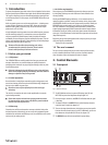
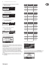
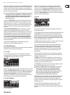
Fig. 2.2: Menu buttons and data wheel
(6) Use these buttons to call up the DCX2496’s menus (e.g. SETUP, RECALL, etc.).
The only exception is the COMPARE button, which allows you to compare
the edits made with the previously selected presets. When COMPARE is
active, no value changes can be entered.
(7) The PAGE buttons select single pages from one menu.
(8) Individual parameters can be selected with the PARAM buttons.
(9) The data wheel allows you to edit the selected parameters.
(10) With the OK and CANCEL buttons you can either conrm or cancel any
settings made.
(11) The PCMCIA card slot is used to exchange les between your DCX2496 and a
PC card with a ash memory.
◊ Please only use “5 V ATA Flash Card” PC cards (min. 4 MB). Even though
the memory capacity of the medium can be selected freely, you can
only store a maximum of 60 presets.
(14) (13) (12)
(15)(16) (16)
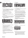
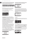
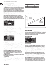
Fig. 2.3: Output LEDs
(12) Outputs 1-6 each have a six 5-segment LED display (plus MUTE, CLIP and
LIMIT LED) showing the respective output levels.
(13) Like the input stages, the output stages should not be overdriven,
i.e. the CLIP LED should not illuminate.
(14) The LIMIT LED illuminates when the limiter for the corres ponding output has
been activated and is operating.
(15) The bottom LED indicator (#8) is the MUTE LED, which illuminates as soon as
the corresponding output is muted (see chapter 4.6).
(16) Output channel buttons, with which you can enter the outputs 1-6
(seechapter 4.5) or mute or reactivate individual outputs in MUTE
mode(4.6).
(17) Use the POWER switch to put your DCX2496 into operation. The POWER
switch should always be in the “O” position when you are about to connect
your unit to the mains.
2.2 Rear panel
(18)
(19)
(20) (21)
(22)
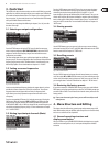
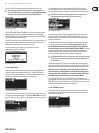
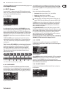
Fig. 2.4: Mains connector and RS-232/RS-485 interface
(18) This is the FUSE HOLDER of your DCX2496. Blown fuses must be replaced by
a fuse of the same type and rating.
(19) The mains connection is an IEC receptacle. An appropriate power cord
isincluded.
(20) The 9-pin RS-232 interface allows you to connect your DCX2496 to a
computer. This enables you to save and load les, update the DCX2496
operating software, or remotely control one or several ULTRADRIVE PRO
units from a PC. Free editor software can be downloaded at behringer.com.
(21) When you have daisy-chained several ULTRADRIVE PRO via the LINK
connectors (see
(22)), please press the TERM switch on the rst and last unit
of the chain, to avoid data reections and transmission errors.
◊ General rule: As soon as one device in the chain is integrated into
the system via only one of the LINK connectors, the TERM switch
must be pressed (ON). Detailed information on this can be found in
chapter 4.2.6 “Miscellaneous”.
(22) Use the LINK connectors A and B (RS-485 network interface)
anda commercially available network cable to daisy-chain several
ULTRADRIVEPROs.
(23)
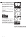
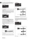
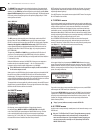
Fig. 2.5: Output connectors
(23) Balanced XLR output connectors for output channels 1-6. Connect your
power amps here.
(24)
Fig. 2.6: Input connectors
(24) Balanced XLR input connectors A, B and C are used for connecting input
signals. Input A can also be used for digital AES/EBU input signals.
InputC can be used for line signals or for connecting a measuring
microphone. IfAUTO ALIGN has been enabled in the SETUP menu
(see chapter 4.2.2), inputC will be set for mic levels automatically.
Additionally, phantom power for the measuring microphone will be
switched on.