


15 ULTRADRIVE PRO DCX2496 User Manual
The following SUM pages are 100% identical to the IN A/B/C pages 2/5 to
5/5 (see chapters 4.3.2 to 4.3.5)!
4.5 OUT 1-6 menu
Press one of the OUT 1-6 buttons to enter the OUTPUT menu of the respective
output. Here, you can set the IN-OUT conguration, X-OVER POINT or, as with the
input signals, the EQ and DYNAMIC EQ parameters.
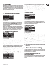
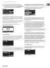
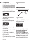
4.5.1 GENERAL
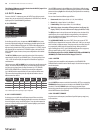
Fig. 4.38: Out 5 ➠ General
On the rst page of this menu, the parameter INPUT SOURCE allows you to
choose the input signal feeding the selected output. Available options are the
inputs A-C and the additional SUM signal. If a STEREO-LINK conguration has
been previously selected in the SETUP menu (see chapter 4.2.1. IN/OUT), inputA
will automatically be routed to the LEFT CHANNEL outputs, and input B to the
RIGHT CHANNEL outputs. However, these preset congurations can be edited
asdesired.
The OUT 16 GAIN parameter controls the volume level of the respective
output channel (also pre-EQ, pre-DYNAMIC EQ, etc.). The setting range is from
-15 to +15dB. Just as the inputs, the output levels should be set properly to
avoiddistortion.
The third parameter, OUT 16NAME can be used to assign specic names to the
outputs. In contrast to the DCX2496 inputs, you cannot enter single characters
here, but you may choose from a list of preset names (e.g. LEFT LOW-MID,
RIGHTHI-MID, SUBWOOFER etc.). Depending on the output conguration
(e.g.LMHLMH) and the output selected, the system assigns a default name.
Thisname can be changed at any time by using the data wheel to select a
dierent name from thelist.
Output-
conguration
OUT 1 OUT 2 OUT 3 OUT 4 OUT 5 OUT 6
LMHL MH Left Lowe Left Mid Left Hi Right Low Right Mid Right Hi
LLMMHH Left Low Right Low Left Mid Right Mid Left Hi Right Hi
L HL HLH Left Low Left Hi Center Low Center Hi Right Low Right Hi
MONO Sub-woofer Low Low-Mid Mid Hi-Mid Hi
Tab. 4.4: Default output names, depending on output conguration
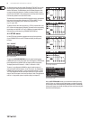
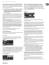
4.5.2 XOVER POINTS
On this page, you can dene the cuto frequencies and lter curves for the
individual outputs, which are displayed graphically for one stereo side and over
the entire frequency range. Use the OUT buttons 1-6 to select the output to be
processed. A frame around the selected OUT number highlights your selection.
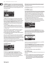
Fig. 4.39: Out 5 ➠ X-Over Points
Use the TYPE parameter in the top left corner of the display to dene the type
of curve at the lower (left) slope. To dene the upper (right) slope, use the TYPE
parameter in the top right corner of the display. Both parameters are marked by
a curve symbol.
You can choose from three dierent types of lters:
1. Butterworth (with a slope of either 6, 12, 18, 24 or 48 dB/oct)
2. Bessel (with a slope of either 12 or 24 dB/oct.)
3. Linkwitz-Riley (with a slope of either 12, 24 or 48 dB/oct.)
◊ With higher slopes, the number of filters goes down (see EQ page 3/6,
display >FREE<). For each 12 dB increase in slope, you will lose 1-2 EQs.
The FREQ parameter in the top left corner of the display selects the lower (left)
cuto frequency for one output. With the same parameter on the right-hand
side you can determine the upper (right) cuto frequency. These parameters,
too, aremarked by a curve symbol.
The XOVER ADJUST MODE, when set to “FREE”, allows you to enter all TYPE
and FREQ values, independent of one another. When set to “LINK”, you can couple
the X-Over lters of adjacent outputs. Though your entries are retained, theywill
be proportionally shifted with each parameter change. When you shift the
upper cuto frequency of OUT 1 in the LMHLMH conguration for test purposes,
thelower cuto frequency of OUT 2 will be shifted as well.
The following pages 3/8 to 5/8 (EQ, DYNAMIC EQ (FILTER) and DYNAMIC EQ
(DYNAMICS)) are 100% identical to the IN pages 3/5 to 5/5!
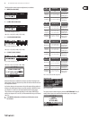
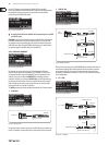
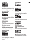
4.5.3 LIMITER
To protect your power ampliers and loudspeakers, the ULTRADRIVE PRO
DCX2496 features a limiter for each of the six outputs. Use this device to suppress
harmful level peaks.
Fig. 4.40: Out 5 ➠ Limiter
Use the LIMITER parameter to switch this function ON or OFF. The corresponding
THRESHOLD parameter determines (similarly to the DYNAMIC EQ) the LIMITER
threshold (-24 to 0 dB). RELEASE controls the recovery time that elapses
between the point when the signal drops below THRESHOLD and the deactivation
of the LIMITER function (20 to 4,000 ms).
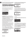
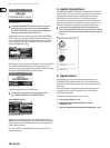
4.5.4 POLARITY/PHASE
Any phase errors at the outputs (cancellation of specic frequency ranges) may
be corrected here.
Fig. 4.41: Out 5 ➠ Polarity/Phase