


10 EUROPOWER PMP1000/PMP4000/PMP6000 User Manual
PMP1000: This does not apply to the mono/stereo combination ◊
channels 5/6 and 7/8.
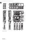
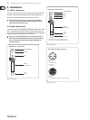
INSERT I/O(20) . Insert points or simply inserts are used to process a signal with
dynamic processors or equalizers. They are pre-fader, pre-EQ and pre-MON/
FX SEND. Unlike reverb and other effects, which are usually added to the dry
signal, dynamic processors usually process the entire signal. So, aux send
buses are not the best solution. Dynamic processors need to be inserted
directly into the signal path. Once processed, the signal then returns to the
mixing console at the same point where it left. Signal interruption takes
place only if a plug is inserted into the corresponding jack (¼" stereo plug:
tip = signal output, ring = input). All mono input channels are equipped
with inserts.
The stereo channels have a GAIN control for gain adjustment, with the input (21)
sensitivity ranging from +20 to -20 dB.
PMP1000: The stereo channels 5/6 and 7/8 feature an additional
XLR connector for microphones whose gain can be set from 0 to +40 dB.
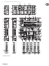
Each stereo channel has two line-level inputs (¼" jacks) for the left and right (22)
channels. If only the jack marked “L” is used, the channel is mono. The signal
will then be reproduced on both sides.
PMP1000: This does not apply to the mono/stereo combination ◊
channels 5/6 and 7/8.
PMP1000: Channels 13/14 and 15/16 are routed to the main mix ◊
without additional tone or volume adjustment. For example, using the
channels 13/14 and 15/16 you can connect a submixer and utilize the
PMP1000’s power amplifier.
PMP4000: The stereo channels 9/10 and 11/12 are equipped with additional (23)
RCA connectors.
PMP6000: The stereo channels 13/14 and 15/16 are equipped with additional
RCA connectors.
PMP4000/PMP6000: Please note that you need to set the A/B selector ◊
(4) to A (¼") or B (RCA) when you connect a signal to the input.
PMP4000/PMP6000: Each of the two stereo channels has two monitor (24)
controls (MON 1/2) and a LEVEL control (25). Like the other channels,
they also feature a PFL switch.
Instead of a fader this channel has a rotary (25) LEVEL control.
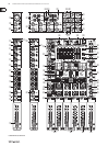
The phantom power supply provides the voltage necessary for the operation (26)
of condenser microphones. Use the PHANTOM switch to activate the supply
for the XLR connectors of the input channels. The +48 V LED will illuminate
when phantom power is on. In most cases, dynamic microphones can still be
used, as long as they are connected in a balanced configuration. If in doubt,
please contact the manufacturer of your microphone!
With phantom power switched on, you must never connect ◊
microphones to the console (or to a stage/wall box). Also, be sure to
mute the monitor/P.A. speakers, before you turn on the phantom
power supply. After switching on, please allow the system to stabilize
for about one minute, before you adjust the input gain.
Caution! Never use unbalanced XLR connectors (pins 1 and 3 ◊
interconnected) on the MIC input jacks, if you are going to use the
phantom power supply.
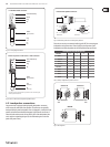
The (27) AMP MODE switch determines the mode of operation of the
PMP amplifier stage:
PMP1000:
MAIN: In the “MAIN” position the mixer works as a stereo amplifier.
MON: In this mode the monitor signal is present at OUTPUT A (71) and the
main signal at OUTPUT B (70) (both are mono).
BRIDGE (bridged mono mode): In BRIDGE AMP MODE the output power
of OUTPUT A is added to that of OUTPUT B, i.e. OUTPUT B delivers twice its
normal output power.
PMP4000/PMP6000:
MAIN L/MAIN R. In position MAIN MIX, the mixer works as a
stereo amplifier.
MON 1/MONO. In this mode the monitor 1 signal is present at OUTPUT A (71)
and the main signal at OUTPUT B (70) (both are mono).
BRIDGE (bridged mono mode): In BRIDGE AMP MODE the output power
of OUTPUT A is added to that of OUTPUT B, i.e. OUTPUT B delivers twice its
normal output power.
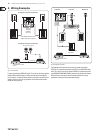
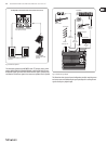
In BRIDGE mode, always connect only one loudspeaker with an ◊
impedance of at least 8 Ω to the OUTPUT B jack! Please note that
OUTPUT A must NEVER be used in BRIDGE mode!
In all other operating modes, the minimum impedance of the speaker ◊
must not fall below 4 Ω.
Please note that the power delivered to the speaker connected to ◊
OUTPUT B in BRIDGE AMP MODE is considerably higher than the power
provided to the speakers wired to the parallel speaker outputs.
Please read the information given on the rear panel of the power mixer.
Information on how to properly connect your speaker with regard to ◊
polarity can be found on the rear of the unit (PIN assignment)
(see also (71) and (42)).
PMP6000: Use the (28) BEHRINGER SPEAKER PROCESSING switch to activate
a filter that allows you to adapt the mixer to the characteristics of your
loudspeakers. If the speakers have a limited frequency response in the bass
range, this function allows you to filter this range at the output signal of the
mixer and thus adapt it optimally to the frequency response of the speakers.
PMP1000/PMP6000: If (29) STANDBY is pressed, all input channels are muted.
During pauses you can prevent the microphones from picking up noise
or interference, which would then be reproduced by the P.A. system or
possibly damage the speaker diaphragms. The benefit is that all faders can
be left untouched while you play back music from CD via the CD/TAPE inputs
(see (55)). There is also no need to move the faders and lose your mix.
Equalizer and FBQ2.2
Your power mixer features a graphic 7-band equalizer, which allows (30)
you to fine-tune the sound depending on the room acoustics. In the
center position the frequency response is not effected. To boost or cut a
certain frequency range, simply move the corresponding fader upward or
downward respectively.
Please note that the equalizer behaviour depends on the position of ◊
the AMP MODE switch (see (27)).