


15 EUROPOWER PMP1000/PMP4000/PMP6000 User Manual
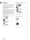
Loudspeaker connections4.3
Your power mixer is equipped with high-quality loudspeaker connectors ,
which ensure safe and trouble-free operation. The connector was especially
developed for high-power loudspeakers. Once it is plugged in, it safely locks into
position and cannot be accidentally disengaged. It prevents the occurrence of
electrical shock and ensures the correct polarity. Each of the loudspeaker jacks
carries only the assigned single signal (see the information given on the rear
panel of the power mixer).
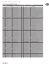
Please be sure to only use commercial cables (type NL4FC) for connecting your
loudspeakers to the power mixer. Please check the pin assignment of your
loudspeakers and cables dependent on the PMP speaker output you choose.
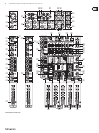
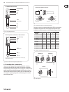
EUROPOWER PMP1000/PMP4000/PMP6000
OUTPUT A 1+ 1- 2+ 2-
MAIN L x x
MONITOR x x
MONO x x
OUTPUT B x x
OUTPUT B 1+ 1- 2+ 2-
MAIN R x x
MONO x x
MONO x x
BRIDGE x x
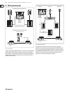
strain relief clamp
sleeve
ring
tip
sleeve
ground/shield
¼" TRS footswitch connector
ring
FX2
tip
FX1
Fig. 4.4: ¼" mono plug for footswitch
strain relief clamp
sleeve
ring
tip
sleeve
ground/shield
Connect the insert send with the input and the insert with the output
of the output eects device.
Power amp insert send return ¼" TRS connector
ring
send (out)
tip
return (in)
Fig. 4.5: Stereo ¼" TRS connector for power amp ISR connection
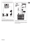
1-
2-
2+
1+
1-
2-
2+
1+
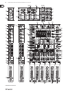
front view rear view
Professional speaker connector
Fig. 4.6: Professional speaker connector with polarity allocation
Tab. 4.1: Polarity configuration of speaker connectors
OUTPUT B
BRIDGE
1+
1+
2+
1+
1- 1-
8 Ω
4 Ω
8 Ω
4 Ω
16 Ω
8 Ω
OUTPUT B
Fig. 4.7: Pin assignment