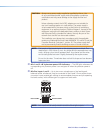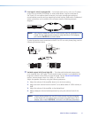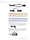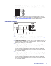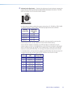
e Line level 3 gain control — Rotating the encoder screw clockwise increases the gain
setting, rotating the encoder screw counterclockwise decreases the gain setting. This
adjustment controls the single gain point in the mix matrix that mixes stereo line level
input 3 to the stereo output bus.
The gain adjustment is indicated by the LED indicator bar (
f
). When the encoder
screw rotation has stopped for three seconds or longer, the LED indicator returns to
the output meter indication.
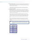
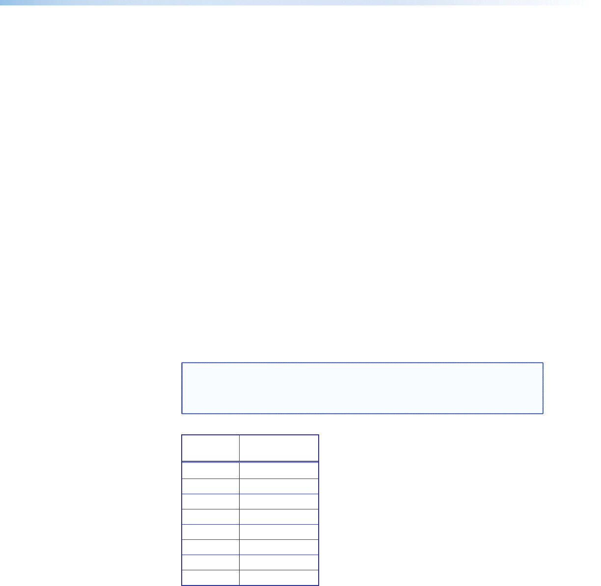
f LED ladder indicator bar — As the mix-point gain or output volume increases or
decreases via the front panel controls, the LED indicator bar lights from the bottom to
the top to indicate the current mix-point or volume level, as shown in the table below.
As the volume is increased or decreased within a volume range, the top LED to be lit
flashes once. If the knob is turned past maximum volume, all 8 LEDs flash for as long
as the knob continues to be turned.
When the output volume is muted, the individual LEDs scroll from the top to the
bottom to indicate a muted state. The LEDs return to being a meter for the output
signal when the audio is unmuted. Unmute occurs when the mute process is reversed,
or when an encoder screw or the volume knob position is changed. All LEDs blink
when the user attempts to adjust the encoder position beyond the maximum gain
level.
When no activity is detected for either the mix-point encoder screws or the volume
adjust knob, the LED indicator bar will reflect a combined L/R output meter level,
where the max level of either left or right meter is always displayed, as shown in the
table below.
NOTE: Mix-point or volume level is only displayed on the LED ladder indicator
whenever the front panel encoder screws or the volume adjustment knob
are being adjusted and not through DSP Configurator software or SIS
commands.
LED Level Meter Display
(dB)
8 -6 to 0
7 -12 to -7
6 -18 to -13
5 -24 to -19
4 -30 to -25
3 -36 to -31
2 -42 to -37
1 -60 to -43
MVC 121 Plus • Installation 9


