Mixer
The DSP architecture contains a mixer that connects the mic/line and line inputs to the
line outputs. The DSP Configurator GUI provides control of the mixer, used to set mix
levels from the post processing inputs to the stereo line output bus. Each of the inputs is
connected to a mix-point and output to the stereo output bus. In general, mix levels are
set relative to each other, achieving a desired blend of input signals at an optimal output
level, close to, but not exceeding 0 dBFS at the line output Volume block level meter.
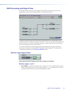
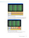
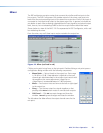
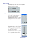
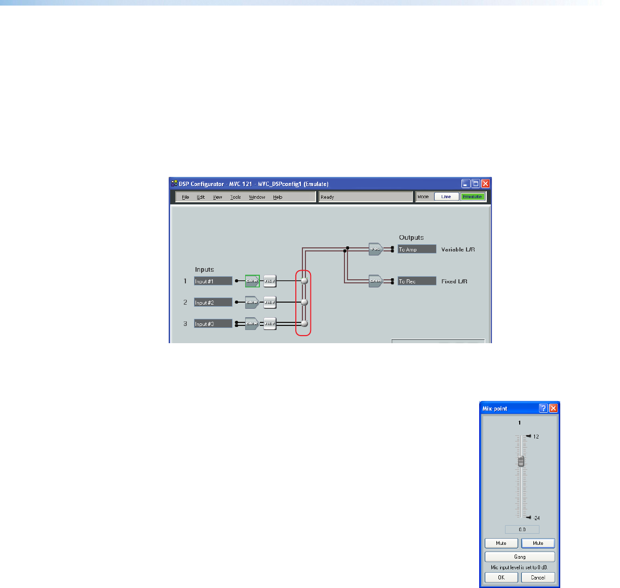
Shown below is a view of the MVC 121 Plus represented in DSP Configurator, with a red
box indicating the mixer.
From the mixer, any or all three inputs may be routed to the output bus.
Figure 14. Mixer (outlined in red)
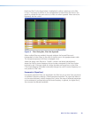
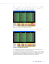
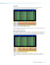
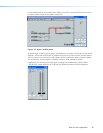
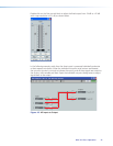
Clicking a mix-point brings focus to that mix-point. Double-clicking a mix-point opens a
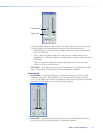
configuration dialog window with the following components:
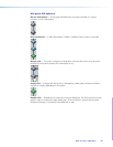
• Mono Fader — Sets mix level to the output bus. Gain range
is -24 dB to +12 dB. Fader behavior is identical to the input
channel gain block described in the mic/line input section with
the exception that coarse adjustment (<Page Up> or
<Page Down>) increases/decreases in 5 dB increments.
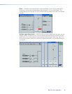
• Mute — Two buttons mute and unmute the left or right signal
to the output bus.
• Gang — Ties the two output bus signals together so that
pressing either Mute button mutes or unmutes both outputs.
• OK/Cancel — Click OK to accept changes and close the
window. Cancel ignores changes and closes the window.
The title above the fader reflects the output channel name for the
mix-point.
MVC 121 Plus • Operation 23


