DX810 – 7
3. INSTALLATION
Connections
Connecting Balanced Sources
Use high-quality three-conductor cable for
balanced connections, such as Star Quad by
Belden, Canare, or Mogami, etc. The better the
shield, the better the audio signal is protected from
induced EMI and RFI.
Note: With screw-down connectors, it’s best to
use stranded wire that is not tinned. Solder can
“flow” under the pressure of the screw-down
terminal and cause the connection to become loose.
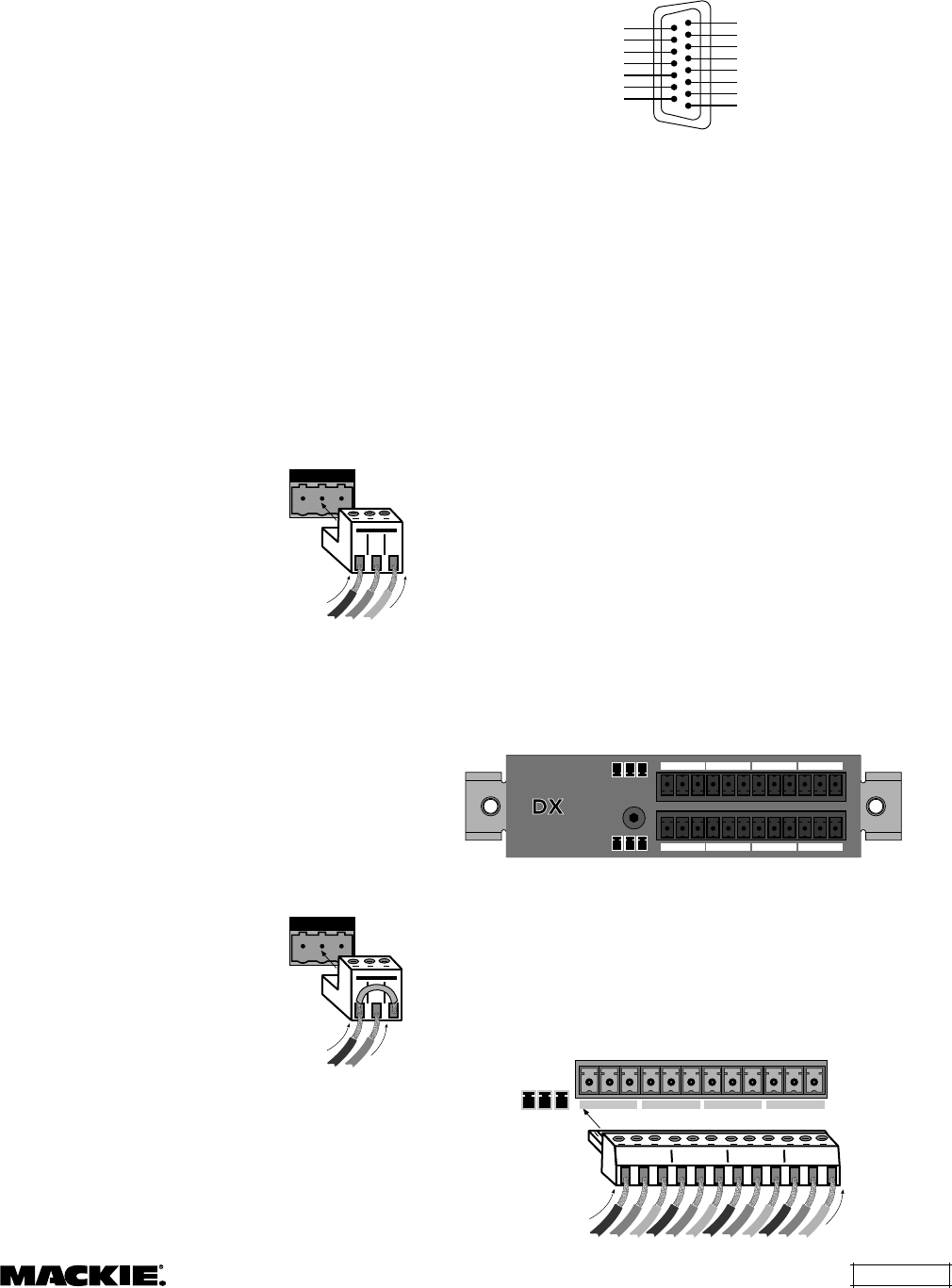
To connect a balanced mic or line-level signal:
Strip the wire back about 1/4" inch. Insert the
wire as far as it will go into the appropriate hole in
the supplied Phoenix-type connector. Tighten down
the screw with a small slot-head screwdriver. It is
recommended that you use 20 or 22 gauge wire
with the Phoenix-type connectors. The connectors
are wired as follows:
Pin 1 = Ground (Shield)
Pin 2 = Hot (+)
Pin 3 = Cold (–)
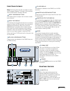
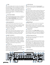
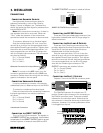
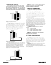
Balanced Connection (Line Input Shown)
Note: To connect to the MIC inputs, turn the
connector upside-down relative to the LINE input
connector. Double check the wiring with the wiring
graphics indicated on the rear panel.
Connecting Unbalanced Sources
It may be necessary to connect a 2-conductor
unbalanced input to a balanced input on the DX810.
To connect an unbalanced line-level signal:
Follow the instructions for connecting a balanced
line-level signal above, but wire the connector
as follows:
Pin 1 = Ground (Shield)
Pin 2 = Hot (+)
Pin 3 = Ground
Unbalanced Connection
Connecting the DIRECT OUTPUTS
This is a 15-pin D-Sub connector. The signals on
the DIRECT OUTPUT are unbalanced. Use shielded,
twisted pairs for the DIRECT OUTPUT cable to ensure
the best rejection of external noise (EMI and RFI).
123
Gnd +
123
Gnd + –
The DIRECT OUTPUT connector is wired as follows:
INPUT 1 HOT (+)
SIGNAL RETURN
SIGNAL RETURN
SIGNAL RETURN
SIGNAL RETURN
SIGNAL RETURN
SIGNAL RETURN
SIGNAL RETURN
INPUT 2 HOT (+)
INPUT 3 HOT (+)
INPUT 4 HOT (+)
INPUT 5 HOT (+)
INPUT 6 HOT (+)
INPUT 7 HOT (+)
INPUT 8 HOT (+)
DIRECT OUTPUTS
1
9
15
8
DIRECT OUTPUTS Pinout Connection
Connecting the RECORD Outputs
These are RCA-type unbalanced connectors. Use
high-quality shielded cable with RCA-type plugs for
these connections.
Connecting the Bus A and B Outputs
These are 3-pin Phoenix-type connectors that
provide a balanced line-level output signal from Bus
A and Bus B. Use high-quality, three-conductor
shielded cable for these connections.
Strip the wire back about 1/4" inch. Insert the
wire as far as it will go into the appropriate hole in
the supplied Phoenix-type connector. Then tighten
down the screw with a small slot-head screwdriver.
It is recommended that you use 20 or 22 gauge
wire with the Phoenix-type connectors. The
OUTPUT connectors are wired as follows:
Pin 1 = Ground (Shield)
Pin 2 = Hot (+)
Pin 3 = Cold (–)
Connecting the Bus C-J Outputs
Outputs C-J are on the DX•10e connector panel.
J I H G
C D E F
•
10
e
–
+
G
G
+
–
The DX•10e Expansion Kit includes two 12-
position Phoenix-type connectors for connecting to
the DX•10e connector panel. These are wired as
indicated on the connector panel. Notice that the
top connector is wired the same way as the bottom
connector; however, it is turned upside-down when
it is plugged into the unit.
G+– G+– G+– G+–
Gnd
Gnd
Gnd
Gnd
+ – + – + – + –
C D E F
–
+
G


