70 Chapter 7: Output Section
VeniceU
Operator Manual
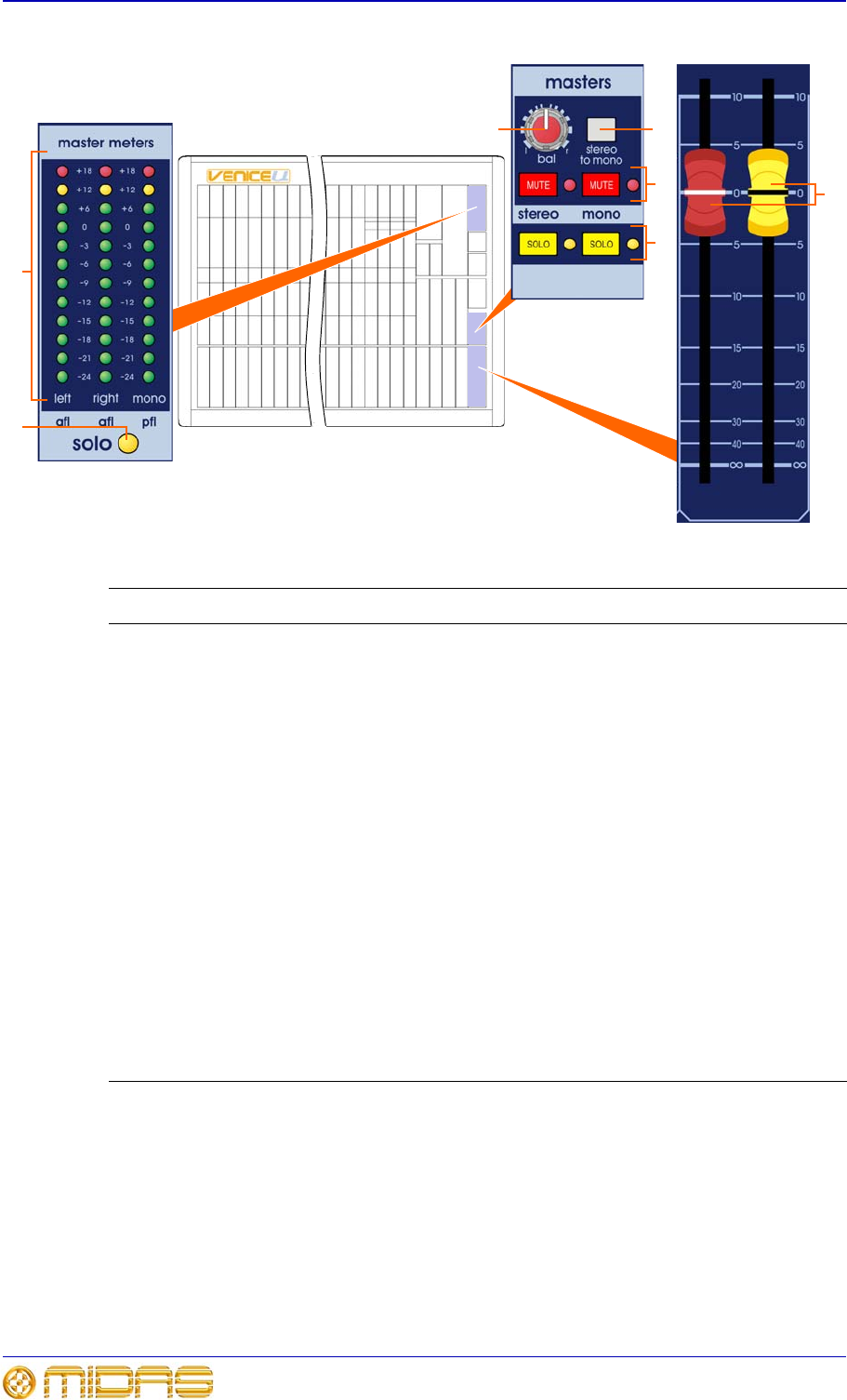
Master outputs sections on the control surface
Item Description
1 stereo to mono switch When this switch is on, a sum of the stereo left
and right signals are routed to the mono signal bus (post-mute and
post-fader, and post-insert points).
2 bal control knob Provides fine adjustment of the left and right power
levels, and can be used during set up to check the left and right channels
separately (by panning fully left or right).
3 MUTE switches and red LEDs These MUTE switches mute the stereo/
mono signals pre-fader. Each red LED illuminates when its mute is on.
4 SOLO switches and yellow LEDs The SOLO switches route the stereo/
mono signal to the PFL mono and AFL stereo buses. The LED for each solo
switch illuminates when its solo is on. Master solo will be overridden by any
other channel/mix solos.
5 Faders These master output faders adjust the output levels, which are
continuously variable from
4 (infinity/off) to +10dB.
6 solo LED This yellow LED illuminates to show when the meters in the
master meters section are functioning as solo meters. The solo bus levels
(afl L, afl R and pfl) are shown on the solo meters. The solo meters are pre-
monitor or phones output mute and level, and are unaffected by changes in
the headphone level or the level sent to the local monitor outputs.
5
7
6
3
12
4


