


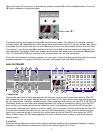

9. Reduction LED
Illuminates when the compressor is reducing the input signal. Use this LED as an indicator while setting your
Threshold level.
MASTER OUTPUT
10. Output Level
Sets the overall output level of the Vocal 100. Do not confuse this control with the compressor’s Gain control
which sets the overall output level of the compressor. The Output Level adjusts the signal level after it has
gone through the effects processor, just before the output jacks. The compressor Gain control is
preprocessor. Certain effects can raise or lower the average level of the signal. Use this control to
compensate for this. Understand that this control is global.—Changing it for one preset will change the level
for all presets.
STEREO PROCESSOR
11. DSP Edge
Global processor EQ that adjusts the amount of high frequency content on the delay and reverb tails.
Sometimes digital processors can make an analog signal sound somewhat bright and/or harsh. We have
included this control to suppress that effect and mellow the signal. This is especially noticeable on delays and
reverbs since they have a decaying tail. Sing into your mic using words containing “s” and “t” while adjusting
the DSP Edge control to hear and tweak this function. Make sure you have selected a preset that contains
reverb and/or delay and the unit is not in Bypass mode. Otherwise, you won't be able to hear your
adjustments. This control will depend largely on the EQ of your PA and your monitors. There is no right or
wrong setting. Simply use what sounds best to you. What you are trying to achieve is a decaying tail that
contains mostly the body of your voice and a hint of the bright consonants.
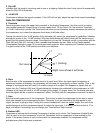
12. Mono/Stereo
Selects a mono or stereo mode for the digital effects imaging. During mono operation, the signals from both
the Left and Right Outputs can be used to power both a main PA and a monitor PA respectively. The Wet/Dry
Mix settings are still functional in the Mono mode, allowing you to separately adjust the amount of effect in
both the main and monitor signals. When in stereo mode the Outputs should be used in a standard Left/Right
configuration. (See EQ on page 14).
13. Up/Down Buttons
Used to select presets when in Play mode, or to adjust parameters when in Edit mode.
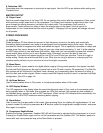
14. LED Display Window
The LED segments in the display show the current bank/preset when in Play mode or the parameter value
being adjusted when in Edit mode. Also included are LEDs that indicate if the presets are user editable or
non-editable factory presets (as well as DSP headroom). When the clip LED indicator blinks consistently, this
indicates that 6 dB of DSP headroom remaining before clipping.
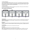
15. Store Button
Used to store the changes made in Edit mode. Upon pressing Store, the display will toggle between “st” and
a preset number. By using the parameter ▲ or ▼ buttons, select the target preset storage location, and press
Store again to complete.
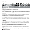
16. Compressor Enable Button
Enables the Analog Compressor. Enabled LED (#8) will illuminate to indicate that the compressor is in circuit.
Pressing the Enable Button again will turn off the compressor and the Enabled LED. This button’s position is
stored with each user preset as long as the Store Button is pressed.
6