


4
<DRB1394>
En
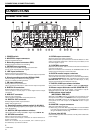
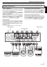
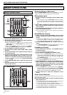
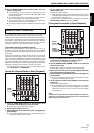
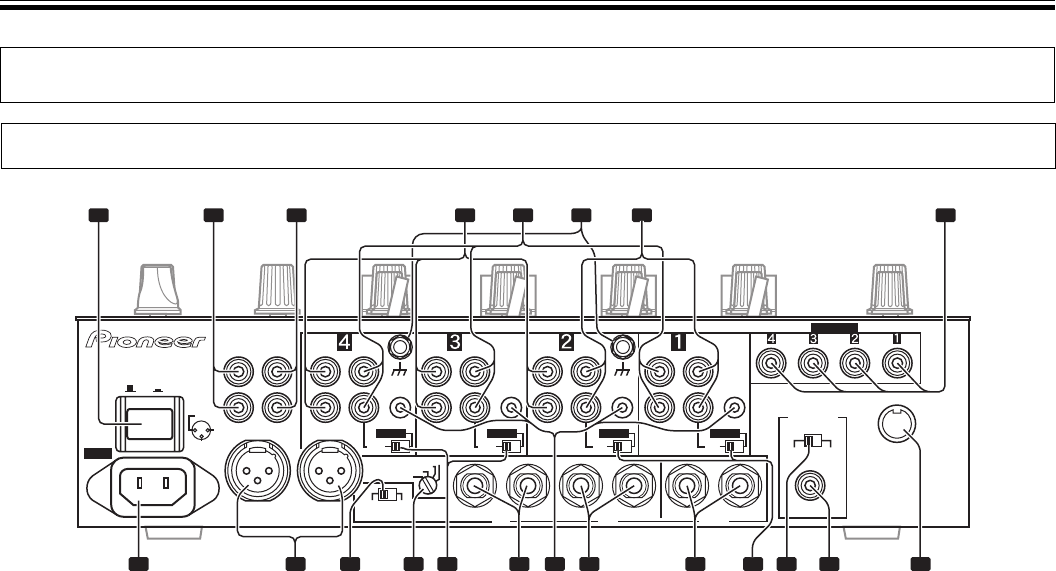
CONNECTION PANEL
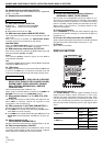
1. POWER switch
2. MASTER 2 output connectors
RCA type unbalanced output.
3. Recording output connectors (REC)
RCA type output connectors for recording.
4. PHONO input connectors
RCA type phono level (MM cartridge) input connectors.
Do not use for inputting line level signals.
5. LINE input connectors
RCA type line level input connectors.
Use to connect a cassette deck or other line level output component.
6. Signal grounding terminals (SIGNAL GND)
Use to connect ground wires from analog players.
This is not a safety grounding terminal.
7. CD input connectors
RCA type line level input connectors.
Use to connect a DJ CD player or other line level output component.
8. DIGITAL IN connectors
RCA type digital coaxial input connectors.
Use to connect to DJ CD player or other digital coaxial output
connectors.
9. MIDI OUT connector
DIN type output connector.
Use to connect to other MIDI component (see P. 19).
10. DIGITAL OUT connector
RCA type digital coaxial output connector.
Master audio digital output.
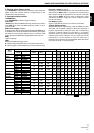
11. Sampling frequency selector switch (fs 48 k/96 k)
Use to set the sampling frequency of the digital output to 96 kHz/24-
bit or 48 kHz/24-bit.
12. DIGITAL/CD input selector switches
Use to select either analog input (CD) or digital input (DIGITAL IN).
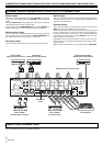
13. RETURN connectors
Ø6.3 mm phone-type input connectors.
Use to connect to the output connectors of external effectors or
similar components.
When the L channel only is connected, the L channel input is
simultaneously input to the R channel.
14. SEND output connectors
Ø6.3 mm phone-type output connectors.
Use to connect to the input connectors of external effectors or other
similar components. When the L channel only is connected, a L+R
monaural signal is output.
15. CONTROL connectors
Ø3.5 mm mini-connector. Use to connect to the control connector of
a Pioneer DJ CD player.
When the connectors are connected, the DJM-800’s fader can be
used to perform start/stop on the DJ CD player.
16. BOOTH monitor output connectors
Ø6.3 mm phone-type booth monitor output connectors.
The sound level from these connectors is controlled independently
by the BOOTH MONITOR level dial, regardless of the position of the
MASTER LEVEL dial. (These connectors are TRS output, so they
support both balanced and unbalanced outputs.)
17. DIGITAL/LINE input selector switches
Use to select either analog input (LINE) or digital input (DIGITAL IN).
18. Master output attenuator switch (MASTER ATT)
Use to attenuate the level of the master 1 and master 2 outputs.
Selectable values are 0 dB, –3 dB, –6 dB and –12 dB.
19. Microphone signal switch
(MIC SIGNAL ADD/CUT)
When set to the [ADD] position, the sounds from microphone 1 and
microphone 2 are output to the BOOTH monitor output connectors.
When set to the [CUT] position, the sounds from microphone 1 and
microphone 2 are not output to the BOOTH monitor output
connectors.
20. MASTER 1 output connectors
XLR type (male) balanced output.
÷ When using a cord with RCA-type plug, users are recommended
to connect the plug directly to the MASTER 2 connectors without
using an XLR/RCA converter plug.
21. Power inlet (AC IN)
Use the accessory power cord to connect to an AC power outlet of the
proper voltage.
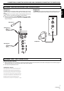
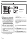
CONNECTIONS
CONNECTIONS (CONNECTION PANEL)
POWER
MASTER 2 REC
RL
R
(TRS)
L
MASTER 1
L
R
PHONO
CONTROL
DIGITAL
MIC SIGNAL
CUTADD
SIGNAL GND
SIGNAL GND
LINE
DIGITAL
LINE
DIGITAL
CD
DIGITAL
CD
LINE
L
R
AC IN
OFF
ON
1GND
3COLD
MASTER ATT
2HOT
PHONO
CONTROL
BOOTH
R
L
(MONO)
SEND
R
L
(MONO)
RETURN
LINE
L
R
PHONO
CONTROL
CD
L
R
LINE
CONTROL
DIGITAL OUT
MIDI OUT
fs (Hz)
48 k 96 k
CD
L
R
-12dB
-6dB
-3dB
0dB
DIGITAL IN
1 2 3 4 5 6 8
9101113 121415161718192021
7