


42
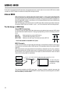
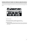
SYSTEM EXCLUSIVE MESSAGE
Status Data Status
F0H iiH, ddH, ....., eeH F7H
F0H: System Exclusive
ii = ID Number: 41H (65)
dd, ..., ee = data: 00H-7FH (0-1 27)
F7H: EOX (End of System Exclusive)
For a detailed explanation, see “ROLAND EXCLUSIVE MESSAGES” and
Section 3.
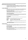
MIDI MACHINE CONTROL (MMC)
Status Data Status
F0H 7FH, 7FH, 06H, com F7H
Byte Description
F0H Exclusive Status
7FH ID Number (Universal Realtime Message)
7FH Device ID (Broadcast)
06H Sub-ID#1 (Machine Control Command)
com Sub-ID#2 (MMC Command)
F7H EOX (End of System Exclusive)
* FC-200 can set the following MMC commands.
com
01H Stop
02H Play
03H Deferred Play
04H Fast Forward
05H Rewind
06H Record Strobe
07H Record Exit
08H Record Pause
09H Pause
* Does not transmit while in EXCLUSIVE Mode.
3. EXCLUSIVE COMMUNICATIONS
Using Roland’s one-way Exclusive message you can transfer data
between FC-200 and another device.
The model ID of the Exclusive message that can be used in the FC-200
is 72H (FC-200). The Device ID can be set with 00H-0FH.
The value is MIDI Channel minus 1.
Request Data 1 RQ1 (11H)
Byte Description
F0H Exclusive Status
41H Manufacturer ID (Roland)
dev Device ID (dev: 00H-0FH)
mdl Model ID (mdl: 72H) FC-200
11H Command ID (RQ1)
aaH Address MSB
bbH Address LSB
ssH Size MSB
ttH Size LSB
sum Checksum
F7H EOX (End of System Exclusive)
DATA SET 1 DT1 (12H)
Byte Description
F0H Exclusive Status
41H Manufacturer ID (Roland)
dev Device ID (dev: 00H-0FH)
mdl Model ID (mdl: 72H) FC-200
12H Command ID (DT1)
aaH Address MSB
bbH Address LSB
ddH Data
: :
eeH Data
sum Checksum
F7H EOX (End of System Exclusive)
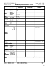
4. PARAMETER ADDRESS MAP (Model ID = 72H)
There are two type of the FC-200 Exclusive message.One is an individual
parameter communication, the other is a bulk dump communication.
In individual parameter communication, One System Exclusive message
“F0 .... F7” can only have one parameter.
PEDAL STATUS (Individual area)
Address(H) Size(H) Data(H) Parameter Description
——————————————————————————————
00 00 00 01 00/7F Pedal 1 Status OFF/ON
00 01 00 01 00/7F Pedal 2 Status OFF/ON
: : : : :
00 09 00 01 00/7F Pedal 10 Status OFF/ON
00 0A 00 01 00/7F Pedal UP Status OFF/ON
00 0B 00 01 00/7F Pedal DOWN Status OFF/ON
00 0C 00 01 00/7F Pedal CTL Status OFF/ON
00 0D 00 01 00-7F EXP Pedal Status 0-127
00 0E 00 01 00-7F Foot SW/EXP 1 Status 0-127
: : : :
00 13 00 01 00-7F Foot SW/EXP 6 Status 0-127
Outputs when pedal is operated while in the EXCLUSIVE Mode.
Also outputs Data Set DT1 when Data Request RQ1 is received.
Data Set DT1 is ignored.
LED STATUS (Individual area)
Address(H) Size(H) Data(H) Parameter Description
——————————————————————————————
01 00 00 01 00/7F Pedal 1 LED Status OFF/ON
01 01 00 01 00/7F Pedal 2 LED Status OFF/ON
: : : :
01 09 00 01 00/7F Pedal 10 LED Status OFF/ON
01 0A 00 01 00/7F Pedal UP LED Status OFF/ON
01 0B 00 01 00/7F
Pedal DOWN LED Status
OFF/ON
01 0C 00 01 00/7F Pedal CTL LED Status OFF/ON
Outputs when Data Request RQ1 is received.
Receives Data Set DT1 only in the EXCLUSIVE Mode.
LED on each pedal changes its status according to received Data Set
DT1.
BANK DISPLAY STATUS (Individual area)
Address(H) Size(H) Data(B) Parameter Description
——————————————————————————————
02 00 00 01 0abcdefg Bank Display Right *1
02 01 00 01 0abcdefg Bank Display Left *1
Outputs when Data Request RQ1 is received.
Receives Data Set DT1 only in the EXCLUSIVE Mode.
Display changes information according to the received Data Set DT1.
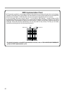
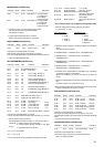
*1 Each bit represents ON/OFF of corresponding display segment.
Bit “0” = OFF; “1” = ON
Segment No. is as follows:
Bank Display
——————————————
| d d |
| — — |
| e | | c e | | c |
| — a — a |
| f | | b f | | b |
| — — |
| g g |
——————————————
Left Right