


43
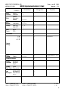
MODE STATUS (Individual area)
Address(H) Size(H) Data(H) Parameter Description
——————————————————————————————
03 00 00 01 00-03 Mode Status *1 0: Program Mode
1: Control Mode
2: Note Mode
3: Exclusive Mode
03 01 00 01 00-03 Mode Status *2 0: Program Mode
1: Control Mode
2: Note Mode
3: Exclusive Mode
*1 Outputs on power-up or when Mode change is made.
Also outputs upon receiving Data Request RQ1.
Data Set DT1 is ignored.
*2 Outputs when Data Request RQ1 is received.
Mode is changed when Data Set DT1 is received.
BANK NUMBER (Individual area)
Address(H) Size(H) Data(H) Parameter Description
——————————————————————————————
04 00 00 01 00-63 Bank Number *1 0-99
Outputs when Data Request RQ1 is received.
Bank Number is changed when Data Set DT1 is received.
The value exceeding the Bank Limit automatically falls to the limit value.
*1 This is not a Bank Select Number.
EDIT PARAMETERS (Individual area)
Address(H) Size(H) Data Parameter Description
——————————————————————————————
05 00 00 01 00000abcB Bank Status *1
05 01 00 01 00-63H Bank Limit 0-99
05 02 00 01 rrH Pedal 1 Assign Message *2
05 03 00 01 rrH Pedal 2 Assign Message *2
: : : :
05 0B 00 01 rrH Pedal 10 Assign Message *2
05 0C 00 01 rrH Pedal UP Assign Message *2
05 0D 00 01 rrH Pedal DOWN Assign Message *2
05 0E 00 01 rrH Pedal CTL Assign Message *2
05 0F 00 01 ccH EXP Pedal Assign Message *3
05 10 00 01 rrH Foot SW/EXP 1 Assign Message *2
: : : :
05 15 00 01 rrH Foot SW/EXP 6 Assign Message *2
05 16 00 01 00abcdefB Latch Status Upper *4
05 17 00 01 0ghijklmB Latch Status Lower *4
05 18 00 01 00-03H Mode Jack Loop *5
05 19 00 01 00-08H Note Range C0-C8
05 1A 00 01 00-08H Octave shift High C0-C8
05 1B 00 01 00-08H Octave shift Low C0-C8
05 1C 00 01 01-7FH Note On Velocity 1-127
05 1D 00 01 00/01H Pedal CTL Latch Status *6 OFF/ON
Outputs when Data Request RQ1 is received.
Value of each edit parameter changes when Data Set DT1 is received.
*1 Each bit has the following meaning.
Each bit represents OFF when it is set at “0” and ON when set at “1”.
0000abcB a: Number pedal is used to select Bank.
b: Outputs Program Change information upon Bank
change.
c: Outputs Bank Select information.
*2 rr = 01-1F, 21-5F, 60-6B
*3 cc = 01-1F, 21-5F
rr and cc data represent output messages to be assigned to pedal.
01-1F, 21-5F: Controller Number (1-31, 33-95)
60, 61, 62: Realtime Message Start, Stop, Continue
63, 64, 65: MMC(MIDI Machine Control) Command
Stop, Play, Deferred Play
66, 67, 68: MMC Command Fast Foward, Rewind,
Record Strobe
69, 6A, 6B: MMC Command Record Exit, Record Pause,
Pause
* Only Controller Number can be assigned to each Expression pedal.
*4 Each bit reflects latch/momentary setting of each pedal:
0 = momentary; 1 = latch
Latch Status Upper Latch Status Lower
00abcdefB a: Pedal 6 0ghijklmB g: Pedal 1
b: Pedal 7 h: Pedal 2
: :
e: Pedal 10 k: Pedal 5
f: Pedal UP l: Pedal DOWN
m: Pedal CTL
*5 Shows the modes selected by foot switch inserted into the MODE
socket.
Each data sets as shown below:
0: PROGRAM Mode -> CONTROL Mode -> PROGRAM Mode -> ...
1: PROGRAM Mode -> CONTROL Mode -> NOTE Mode ->
PROGRAM Mode -> ...
2: PROGRAM Mode -> CONTROL Mode -> EXCLUSIVE Mode ->
PROGRAM Mode -> ...
3: PROGRAM Mode -> CONTROL Mode -> NOTE Mode ->
EXCLUSIVE Mode -> PROGRAM Mode -> ...
*6 Parameter which changes Pedal CTL Latch Status only. Latch Status
can also be changed by *4 Latch Status.
When both parameters are received, the status of the latter has
priority.
*7 When the massage assigned to the pedal contains information other
than
Controller Number, Latch cannot be turned on.
*8 When transmitting EDIT parameter messages in sequence, the interval
between messages must be 20 msec or longer.
FLIP-FLOP STATUS (Individual area)
Address(H) Size(H) Data(H) Parameter Description
——————————————————————————————
06 00 00 01 00/7F Pedal 1 flip-flop OFF/ON
06 01 00 01 00/7F Pedal 2 flip-flop OFF/ON
: : : : :
06 09 00 01 00/7F Pedal 10 flip-flop OFF/ON
06 0A 00 01 00/7F Pedal UP flip-flop OFF/ON
06 0B 00 01 00/7F
Pedal DOWN flip-flop
OFF/ON
06 0C 00 01 00/7F Pedal CTL flip-flop OFF/ON
Outputs when Data Request RQ1 is received.
Flip-flop of each pedal changes when Data Set DT1 is received.
Indicator lights if pedal flip-flop is ON while in the CONTROL CHANGE
Mode.
*1 Ignored if the pedal is set at momentary.
NOTE RANGE STATUS (Individual area)
Address(H) Size(H) Data(H) Parameter Description
——————————————————————————————
07 00 00 01 00-08 Current Note Range C0-C8
Outputs when Data Request RQ1 is received.
Current note range is changed upon receiving Data Set DT1.
*1 This is not an Edit parameter.